 |
5U 266 Source Of |
|
I built the 5U R266 Source of Uncertainty. This three PCB set has six separate functional sections consisting of a noise source with pink (-3dB), white (+3 dB), and integrated noise (0 dB), fluctuating random voltages (FRV), quantized random voltages (QRV), stored random voltages (SRV), a dual sample & hold (S&H), and a voltage controlled integrator. There are multiple board configurations for 5U, 200 series, and Euro format. There are five forums on Muffwiggler - [ORDER] Buchla format 266 panels for Romans PCBs, [CLOSED] Buchla style & format panels (258, 292, 281, 19, ORDER THREAD: 266-style PCBs, BUILD THREAD: 266-style PCBs and MOTM 266 Source of Uncertainty (Roman F) coming soon. The BUILD THREAD get confusing as all board configurations are discussed in the forum. There is also an Electro-Music Buchla Source of Uncertainty 266 forum for a press-n-peel version as well.
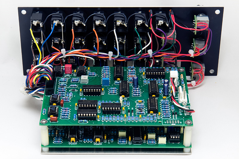
The Roman Filippov PCB 1 (266c-5U-1 v1.1) contains the stored random voltages, dual sample & hold, and the voltage controlled integrator. PCB 2 (266c-5U-2 v1.1) contains the noise source, fluctuating random voltages, and the quantized random voltages. PCB 3 (266c-5U-3 v1.1) contains the front panel jacks, potentiometers, LEDs, and level shifters.
The front panel board is large and formatted for an MU style panel. For a MOTM style panel it requires 4U and I didn't want to dedicate that much space to this module. I have other modules with noise, sample & hold, fluctuating random voltages (e.g. Wogglebug), and various programs for my ComputerVoltageSource which generate random voltages. I built this as a two board set and eliminated the circuitry on PCB 3. Due to the amount of detail for each functional section I have a separate web page for each PCB.
PCB 1 SRV, S&H, & CV Integrator operation and modifications
PCB 2 Noise source, FRV, and QRV operation and modifications
Module power consumption: +15 @ 118 mA, -15V @ 100 mA (vactrol LEDs on, no output LEDs). I changed the resistors for yellow and amber LEDs to 330R to better match the brightness of the red LEDs. The +15V power consumption with all LEDs active increases to about 125 mA.
266 Source Of Uncertainty description from the Buchla Synthesizer User Guide, November 16, 1981
![]() Source Of Uncertainty
demo
Source Of Uncertainty
demo
This is the 266 Source of Uncertainty driving two VCOs. The QRV
2N output goes to the integrator to the S&H which is clocked at 8X the rate
of the QRV. The S&H will alternately clock rising or lowering CVs due
to the integrator lag. The S&H outputs go to a dual quantizer to two VCOs to
two separate spring reverbs and finally to left and right phasers. The VCOs have
a bit of portamento and vibrato and the QRV CV is modulated by a 0 to +5V LFO to
generate some random rising and falling stereo sequences.
Construction
I made a bracket out of 0.050" aluminum to mount the PCBs. The LEDs fit by pressure into slightly undersized holes. I used FCI mini-latch connectors which were slow to crimp and solder. The front panel wiring was quite tedious.
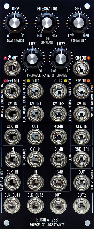
Panel
I managed to fit this into a 2U MOTM style panel. I changed SRV Out2 legend to Sum Out and the SRV Out1 legend to Stp Out since they are unique and this is easier to identify the difference. I also chose to add the 0 to +5V noisy triangle output since I had room for one more jack and labeled it Rnd Tri.
5U 266 FrontPanelExpress design file
I used this design file and created a panel with holes, a single 0.2mm HPGL, and a single 0.4mm HPGL as explained in this Muffwiggler forum topic. It results in a 26% savings!
5U 266 FrontPanelExpress HPGL design file