 |
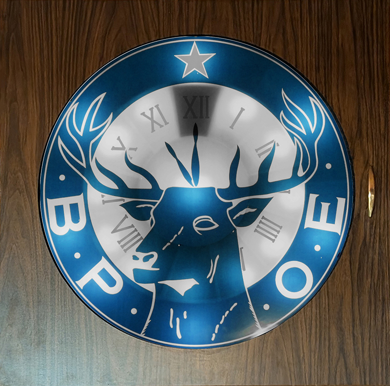
Sherwood Elks #2342 11th Hour Clock |
|
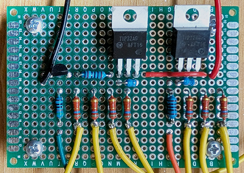
I've worked with a number of Lodges in rebuilding their 11th hour clocks. Some are not the smaller traveling clock. These have a need to drive more than a single LED for illuminating major sections. The sink transistors and this board was not designed for this. I sketched up a PNP circuit using a TIP32 transistor that can drive multiple 1W LEDs.
Soon after, our 11th hour clock at the Sherwood Lodge died. It is a larger wall clock that I needed to rebuild.
Inside it used twenty-nine 10 watt incandescent lamps.
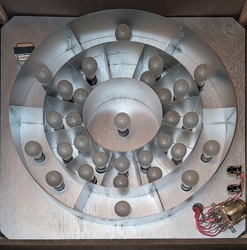
The clock has an outer ring which lights for the entire sequence. At the end with the chimes the center light and all the hours would light (which is the second hour bulb).
This replacement design cannot light all the hour LEDs together since there is a single hour LED dropping resistor, but I decided that was not really necessary for operation. I did want to control more than just a center light. I was able to use one unused pin on the microcontroller for an additional output. Since I needed multiple LEDs, I could not use the on-board center LED resistor and repurposed this connection for the extra logic output. Adding one more PN32643 transistor to the PNP follower circuit allowed the control of another section of multiple LEDs.
This clock runs on a switched outlet so there was no need for the switch input. This also saves wear on the power supply as it is not powered on continuously. On power up, 3 LEDs illuminate the center and the B.P. and O.E. sections, and the hour chime sequence begins. When the sequence reaches the ending chimes sequence, 4 additional LEDs light the bottom and top outer ring areas. All LEDs stay lit for 30 seconds and then turn off. The clock requires a power cycle to restart.
These 1W LEDs are driven at about 330 mA, so four LEDs is about 1.3A collector current. The TIP32AG is able to handle that amount of current without a heat sink. Øja is 62.5 °C/W. The transistor is saturated so Vce is <1V so dissipation is only ~1W so Øja is about 62 °C. This makes the junction < 90 °C which is 60% of maximum. Besides, they are only on for about a minute. I could only measured a couple of degree rise on the TIP32AG. This clock does require a 5V 5A power supply.
Additional LED driver schematic (PDF)
This photo shows the LEDs mounted on the front. I also reinforced the corner bracing as it was originally glued together.
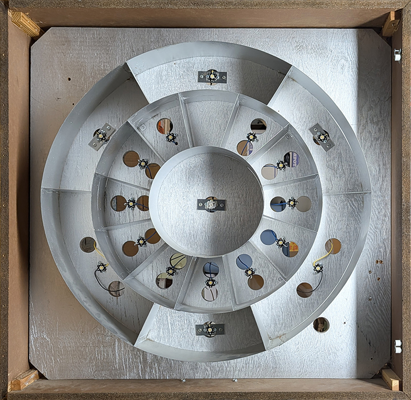
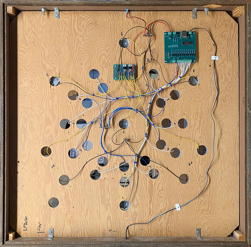
This photo shows the wiring and the additional lights hand-wired board. The wire to the bottom originally went to the speaker but I later moved it from the bottom to a side due to limited clearance. I mounted the power supply on the top with double-adhesive tape.
My learning from all of this is there are quite a number of different style and size 11th hour clocks. What would be interesting is what the Elks did prior to electricity for the 11th hour ritual.