|
Blacet Research |
|
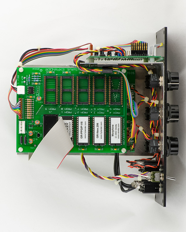
I constructed my MiniWave with a Stooge front panel setup for a Hylander ROM expander board and a Tellun JLH2090CV board.
I have these ROMS installed:
ROM-0: Miniwave
ROM-1: Socket Rocket
ROM-2: GR-PPG/P-V5
by Grant Richter
ROM-3: GR-New.256
by Grant Richter
ROM-4: Morphine
by Mathew Davidson
ROM 5: Serge Creature "Pocket Monster" by paperkettle.com
ROM 6: Schumann PLL by paperkettle.com
ROM 7: Commodore 64/NES "ROM1" by paperkettle.com
ROM 8: Ensoniq SQ80 Wave1 by Patrick Joericke
ROM 9: Ensoniq SQ80 Wave4 by Patrick Joericke
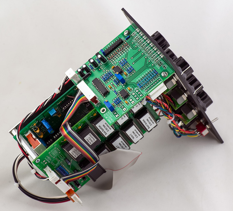
I brazed together several pieces of aluminum to build the chassis to mount these three boards to the front panel.
As I added more ROMs I had trouble with reliable operation which was due to the chip enable of ROM-0 not meeting the Vih specification of 2 volts. R18 pulls up this chip enable to VLED which was less than 2 volts with the forward voltage drop of the LEDs I used. I corrected this by connecting R18 to +5 volts instead.
Here is my MiniWave waiting for 5 more ROMs.
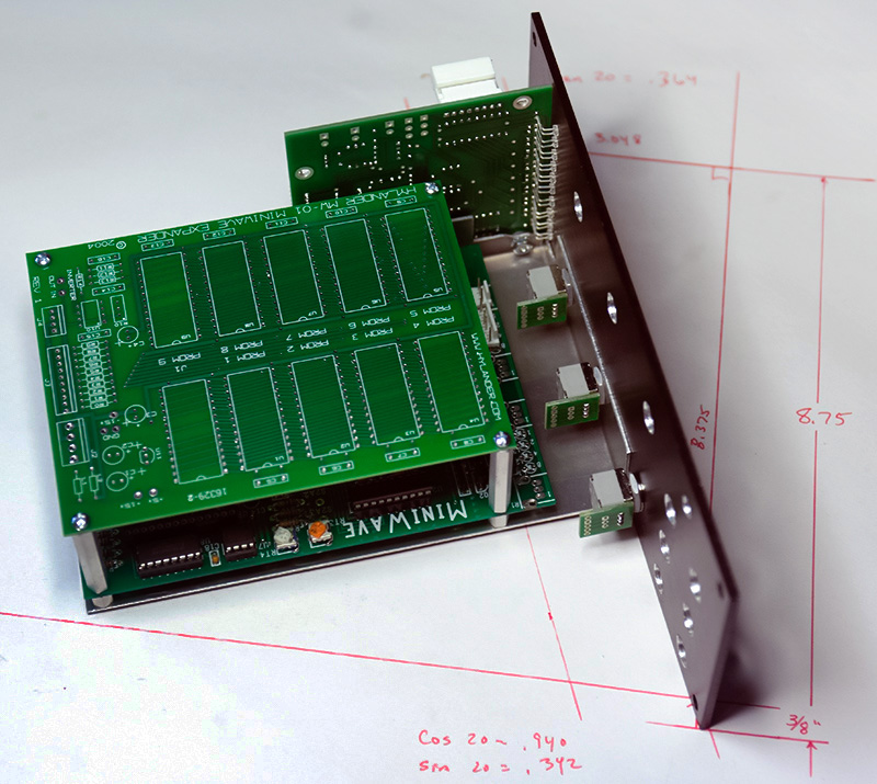
Second Build
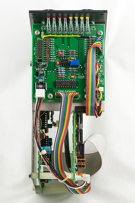
I built another 5U MiniWave with both the Hylander and Hendry PCBs. This module had to fit into a slant Synthesizers.com cabinet. The cabinet face slopes at 20 degrees and the bottom flange is routed 3/8" into the bottom thus reducing the available space. I had to mount the Hendry board between the LEDs to have enough height to mount the MiniWave PCB. I had to space the Hendry PCB 0.115" above the bracket so all the leads had to be trimmed off very close. I could not use enclosed jacks for the bottom row. This module just barely fits. Wiring was a challenge because everything was so close together. I used the inverter on the Hendry board and not the Hylander board. I made a bracket to mount all three boards to.
This module was to be used with a Dotcom power supply so I needed the 6 pin 0.100" MTA male connector. I ended up piggybacking it on the MTA connector and bending the pins to fit. I filled the gap with epoxy. The connector with cable attached is just a bit wider than the module.
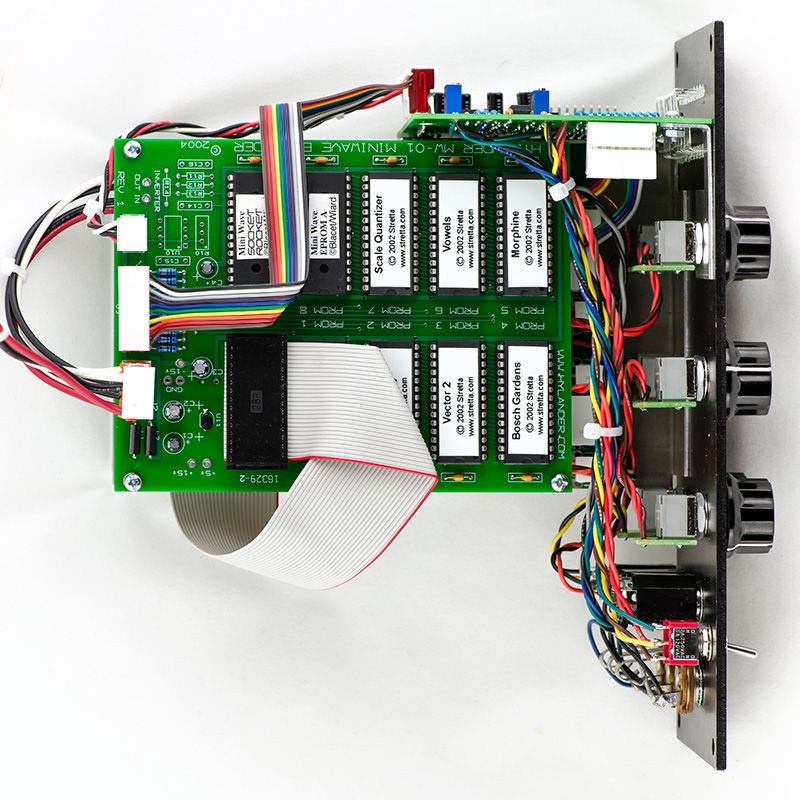
I mounted some of the MTAs reversed and on the bottom side of the PCB to improve the wiring. I also used MTA connectors on the MiniWave for the potentiometers and LEDs.