|
4U 200 Series Format Joystick |
|
I wanted an easier mechanism for control of signals than potentiometers on panels buried by cables. The 204 Quad Spatial Director was overkill for my needs and I didn't want joysticks mounted on a vertical panel. I decided to design my own joystick interface where the joysticks could be remote in a small enclosure.
Initially I wanted to design the joysticks so both the minimum and maximum voltages were adjustable over the range of -15V to +15V. I also wanted a way to easily set these voltages. I found lots of 2 and 3 wire small 3 digit LED voltage modules, but none that would display negative voltages. I could augment these displays with a full wave rectifier and a comparator to drive a rectangular LED as the negative symbol but this was more circuitry than I wanted to hand wire. I also looked into writing a program to display four +/- 3 digit voltages on a 16x2 LCD panel. In the end I decided that this module was getting too complex and so simplified it.
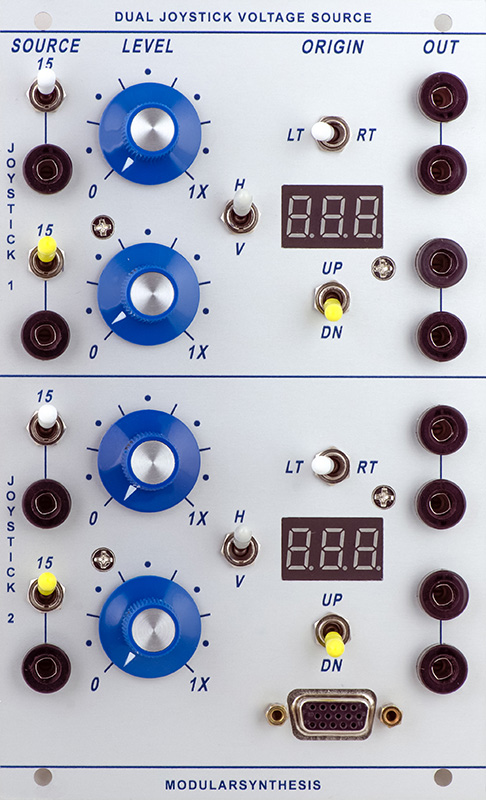
The resulting design supports two joysticks where each axis can be set over a range of 0 to +15V. A switch sets the origin for both axis so operating the joystick will increase or decrease this control voltage. Although there are four controls, I only used two LED voltage modules using a switch to select the axis to be measured.
I added another switch to select either +15V or an external input as the source. This allows me to use this module as a general purpose quad attenuator. Both the control and joystick determine the amount of attenuation using an external input. I used rail-rail op-amps so I could operate over a 0 to +15V range or a +/-15V range with the external input.
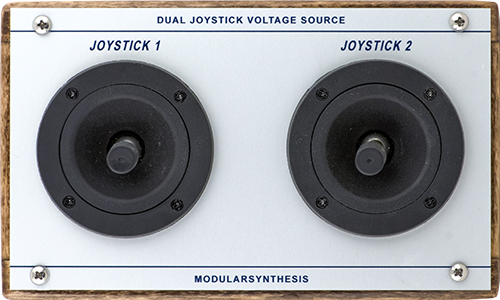
I designed two FrontPanelExpress printed panels, a 1U panel and a smaller joystick panel.
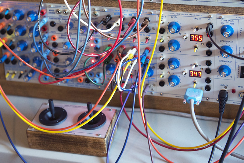
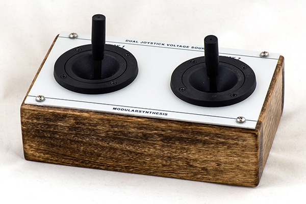
The joysticks are housed in a small wood cabinet. It connects to the panel with a 12 conductor high-density D-sub connector. 12 conductors are needed due to the origin switching.
Construction
I used rail-rail op-amps so I could have a range of 0 to +15V. Costs for the components have significantly increased this past year. Rail-rail DIP op-amps and the joysticks have doubled in cost. C&K DPDT switches have also significantly increased. The +15/ext requires DPDT switches to disconnect the LED voltage monitors since the input could be bipolar or negative.
The schematic is relatively simple. The control is driven by either +15V or the external input. It is buffered by a rail-rail op-amp for a low impedance output. A DPDT switch reverses the joystick potentiometer terminals. The joystick wiper is buffered by another rail-rail op-amp. The LED voltage monitor is wired to the outputs but could be wired to the attenuated control voltage.
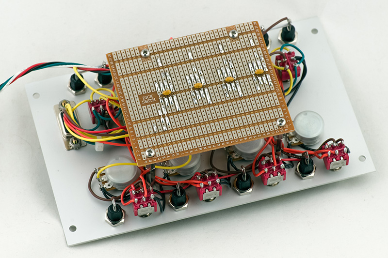
Most of the wiring is on the panel. The PCB consists just of 8 voltage followers.
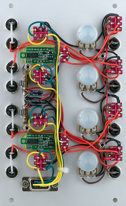
The PCB wiring is fairly simple. The OPA275 rail-rail op-amp has a maximum input of 13.5V. I attenuated the input to 85% for a maximum of 12.8V and increased the output gain to 1.18X to compensate. At 12.8V I could have used a TL072 for the input buffers, but chose to use both sections in the package for a single channel.
DJB-Dual Joystick 1/2 schematic
DJB-Joystick FrontpanelExpress Design Files .zip which includes the .png graphics since I don't believe you can extract them from the .fpd files.