|
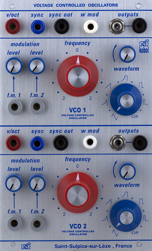
RSF Kobol Dual VCO Module |
|
I was sent a RSF Kobol dual VCO to repair. I didn't have any knowledge of the Kobol Expander and there is very little information on the web. The waveshape control had way too much range, the frequency control was too coarse, and it needed calibration and other minor repairs.
The schematics available on the web are mostly unreadable but I cleaned up half for one VCO. While still unreadable, it gives an overview of the architecture of the VCO and waveshaper. I was also able to find a redrawn schematic for the waveshaper.
Kobol Expander single VCO schematic
Redrawn Kobol Expander waveshaper
I determined that the waveshape control was a +/-15V control with a very narrow range of about +/-1.5V of control. I located the op-amp for this control and reduced the gain to match the panel legends with the exception of Off. I don't know why one would want to narrow the pulse to 0% and so left the control with a very narrow duty cycle at full clockwise rotation. The output level and DC offset changes between the various waveshapes so I AC coupled the 3.5mm output jacks with a 1M bleed resistor to provide a 0V DC level output. I left the banana jack output with the DC coupled signal.
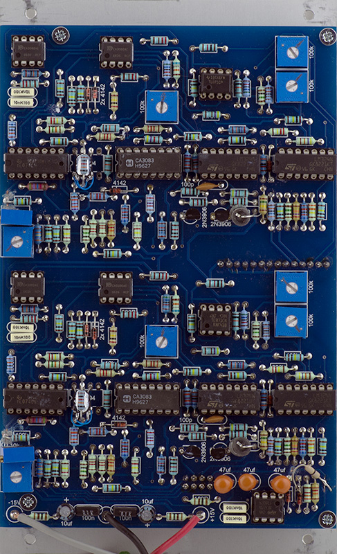
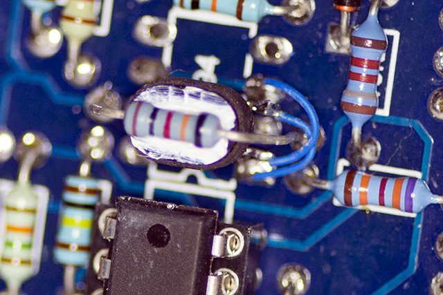
I rebuilt the expo-pair and tempco by eliminating the socket and soldering the transistors directly to the PCB. One has to be rotated to align the flat sides so I flew wires for the outer two leads. A small circle of heat shrink holds the transistors together nicely and the tempco can be routed across the top with a bit of heat sink grease.
The range of the frequency control had been modified and I was able to decrease the range to 4 octaves to match the nomenclature on the panel. This brought the resistor value back to the value on the PCB so I assume this is how the module was designed. I set the initial frequency to C at ~262 Hz at the center position which gives a nice range of about 60 Hz to 1100 Hz with a reasonable fine adjustment.
I could figure out four of the five trimmers. There is a scale and initial frequency trimmer, a triangle symmetry trimmer, and a square and 2X ramp symmetry trimmer. The latter adjusts the duty cycle when the triangle is morphed into a 2X frequency saw. I could not determine the exact function of the center trimmer. There are various setting of the waveshape control that cause the output to have some FM jitter. This control tended to minimize that jitter so that is how I set it.
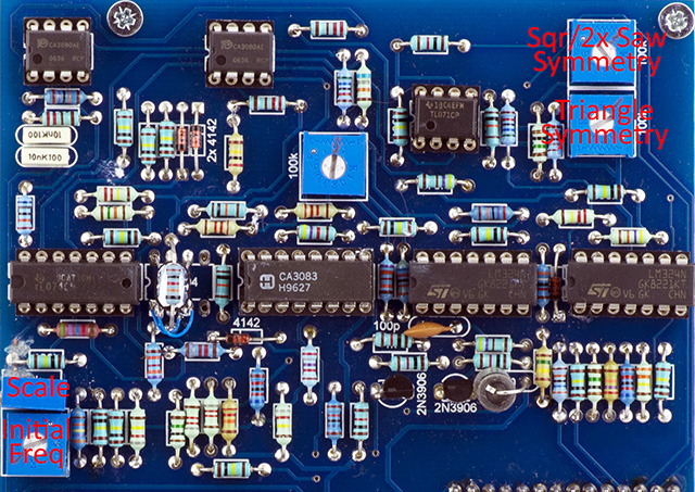
There are no decoupling capacitors that are readily visible on the PCB and the two VCOs do interact. As the waveshape control began to induce some jitter, changing the frequency of the other VCO would eliminate the jitter. I never investigated this further and suspect the power layout and decoupling are the primary issues . I suspect all these modules have the same issue.
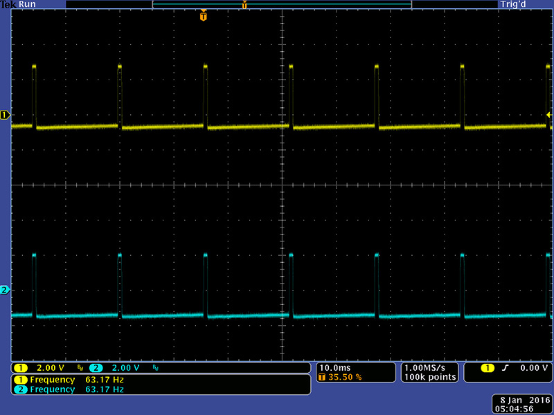
Operation
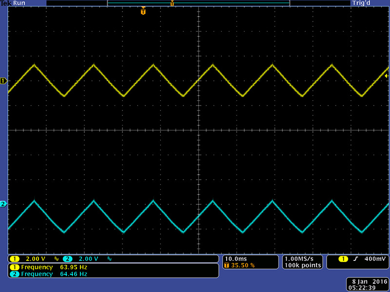
The yellow trace is the AC coupled 3.5mm output and the cyan trace is the DC coupled banana jack. You can see the negative offset of the cyan triangle waveform.
The saw waveform is not quite ideal and you can see the positive offset of the cyan saw waveform.
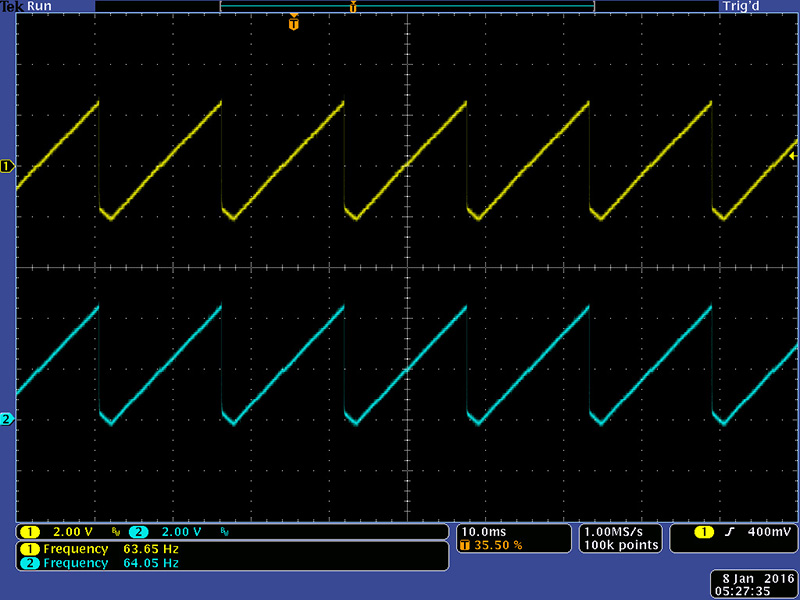
The saw can be morphed to a 2X frequency but with half the amplitude. There is quite a bit of DC offset in the cyan 2X saw waveform.
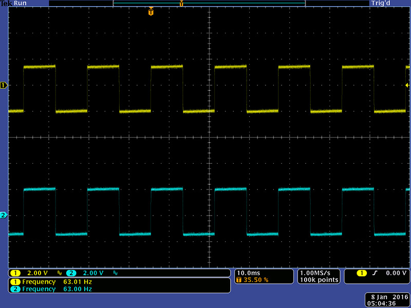
The square wave is nicely formed and there is no DC offset in the cyan square waveform. The yellow square waveform is AC coupled and there is no noticeable tilt.
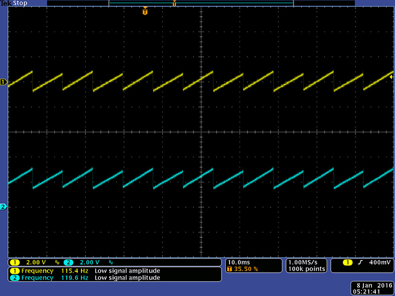
The far clockwise rotation of the waveform control produces a narrow pulse.