|
Flight Of Harmony Plague Bearer Module |
|
I ordered the PBBP Plague Bearer barebones pack from Flight Of Harmony. There are lots of Plague Bearer topics on the Muffwiggler Flight Of Harmony forum and a specific topic for the Plague Bearer Bare Bones Kit. I thought about a dual Plague Bearer in a 1U panel but decided to go with just a single module.
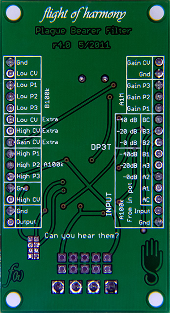
The PBBP barebones pack consists of the PCB, potentiometers, knobs, 3.5mm jacks, and MTA connectors. The design appears to be a single stage Twin T band pass filter with CV control for each T cell and an overall CV gain control. The filter is followed by a buffer with a limiter that can be enabled or disabled by two jumpers. The input signal is attenuated by a 100K potentiometer followed by a selectable 1:1, 10:1, or 100:1 attenuation switch.
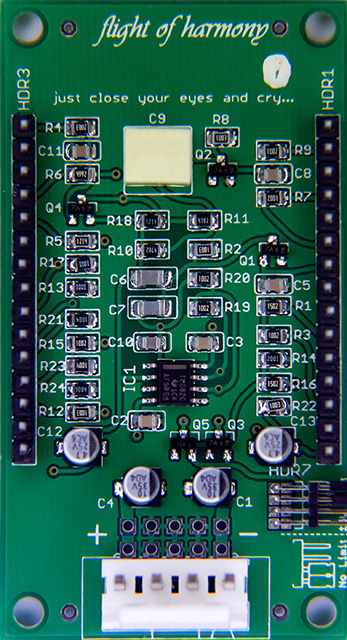
The PCB is small and mostly surface mount components. Power consumption measured ~4.5 mA on both the +15V and -15V supplies.
There are a couple of errors on the R4 wiring diagram and the PCB silk screen.
|
Error |
Correction |
|
The Low potentiometer is shown to be A1M on the wiring diagram and B100K on the PCB silk screen. |
The wiring diagram is correct. The Low potentiometer is A1M. |
|
The Gain potentiometer is shown to be B100K on the wiring diagram and A1M on the PCB silk screen. |
The wiring diagram is correct. The Gain potentiometer is B100K. |
|
The A and B legends on the switch in the wiring diagram differ from the PCB silk screen. |
The switch wiring diagram is correct but legends on the switch are reversed. There are several errors for the switch on the PCB silk screen. This Photoshop image shows the correct legends for the switch. |
 |
|
|
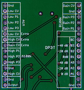
The DP3T and Input legends on the PCB silk screen are wrong - the pin legends are by the wrong pins and the dB legends are by the wrong pin legends. |
The wiring diagram is correct but the PCB silk screen has a number of errors for the DP3T switch. This Photoshop image shows the correct silk screen for the potentiometer values and the DP3T switch. |
|
|
|
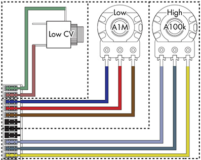
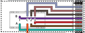
| The P1 P2 P3 order does not match between the wiring diagram and the PCB silk screen for the Low and High potentiometers. | The PCB silk screen is correct but the Low and High control P1 and P3 pins are swapped on the wiring diagram. This Photoshop image shows the correct wiring for the Low and High potentiometers |
|
|
|
The input attenuator is very important as you get different timbres at different input levels. The switch attenuator after the input potentiometer allows a full range of control for the three attenuation settings but I will just use the input potentiometer. It seems to work just fine.
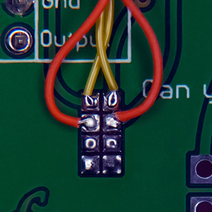
I wanted the limit to be selectable so I added a panel switch. The jumper pads are tiny so I soldered 30 gauge wires to the pads and wired them to a 4 pin MTA connector on a a small daughter board that mounts between the top two PCB mounting holes.
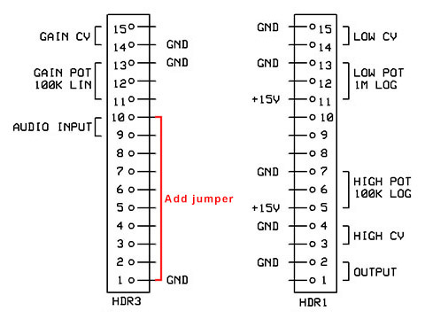
The kit comes with two 15 pin MTA connectors that I replaced with individual 2 pin MTA and 3 pin MTA connectors for the jacks and potentiometers to make the panel wiring easier. This diagram shows the connectors using 2 and 3 pin MTA connectors. Pin 10 has no connection so I jumpered it on the back of the board to ground for the audio input connector.
Construction
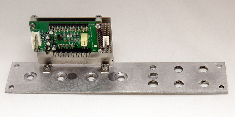
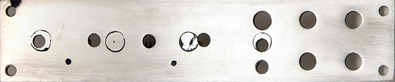
I decided to make my own panel and repurposed a MOTM-320 panel by shearing it in half and stripping the paint. I brazed the four potentiometer holes closed and drilled the additional mounting, potentiometer, switch, and jack holes. I milled the rear of the panel in 1mm for each of the potentiometers as the bushings barely fit through a 3mm panel. I couldn't use the potentiometers to mount the bracket so I added two studs to the panel. In this photo you can see three of the four potentiometer holes I brazed closed, the rear milling for the potentiometers, and the small daughter board with the limit connections for the front panel switch.
The front shows the four holes I brazed closed and the glazing used to fill imperfections.
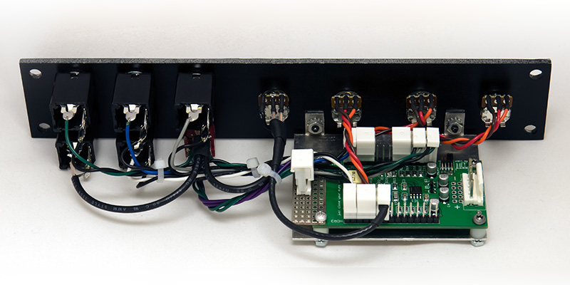
I painted the back of the panel but not the front since it will be covered with a legend overlay. Here is the finished wired module with shielded wiring used for the input. Using individual MTA connectors allowed me to switch the connector orientation to best fit the routing. The potentiometers have been oriented so the knob setscrew fits against the edge of the slot in the shaft.
Operation
The High control varies the amount of ringing while the Low control varies the amplitude and position of the large dip. You can get some different timbres using this module.

Here is a short video of the Plague Bearer being modulated by a tri-phase sine wave LFO. The module generates different timbres but as you can see in this video they are very dependent on the control voltage and change rapidly with small variations in voltage. Using the controls provides much more subtle adjustment of the timbre.
Panel
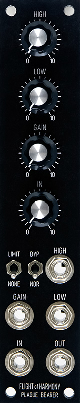
The panel is 1U using small knobs with a limit and bypass switch. I used C&K switches as they are narrower than NKK or Mountain as there is no clearance between the each switch and the jack. The design file includes the 1mm cavities on the rear of the panel. Note the image is an actual photograph of a panel made by gluing a laser print of the FPE design to an aluminum panel and lightly coating with lacquer.
DJB-Plague Bearer FrontPanelExpress design file
Here was my concept for a dual Plague Bearer in a 1U panel. The spacing is the same as my Jürgen Haible scanner chorus/vibrato module. It is tight but doable.
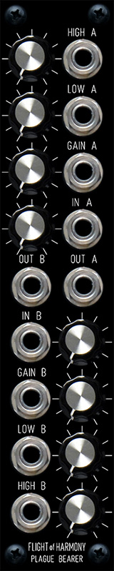
DJB-Dual Plague Bearer FrontPanelExpress design file Design not verified