 |
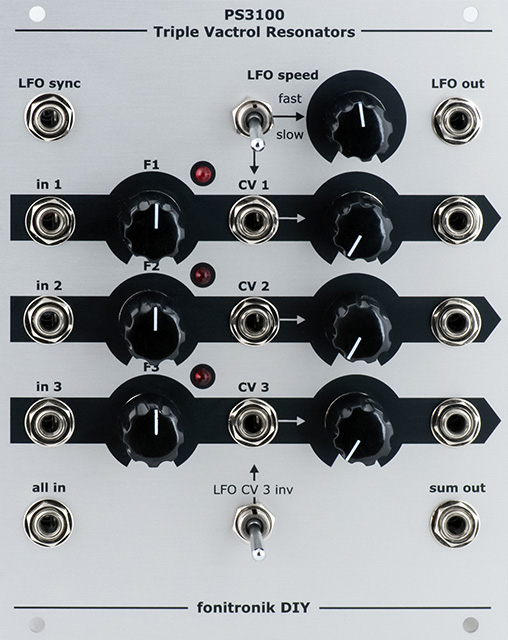
Fonitronik mh21
Triple Resonator |
|
I recently built a pair of Fonitronik mh21 Triple Resonators in the Eurorack format. There are a number of web pages for variations of this resonator but the main forum topic for this module is at [PCBs/Panels] Resurgence of the PS3100 Resonators (mh21).
Assembly was straightforward but lead spacing is critical on this PCB. Resistor footprints are 7mm LS so standard 1/4W resistor are a bit too wide. I used the KOA Speer Mouser 660-MFS1/4DCT52R series resistors which have a smaller footprint. All film capacitors footprints are 5 mm LS. In this photo you can see some of the standard 1/4W resistors and film capacitors that were a bit too large. The BF245 FET was out of stock so I used an NTE312. I've updated the BOM that was uploaded to Muffwiggler with what I think are better components. Some I ordered so I know are correct but some I did not order so I've marked those as unverified. You will need to verify thickness and lead spacing.
Updated Mouser BOM unverified
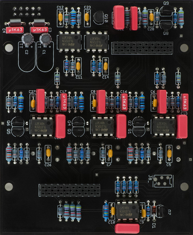
The three trimmers on the rear have a 5mm x 10mm spacing so I simply bent the trimmer leads to fit.
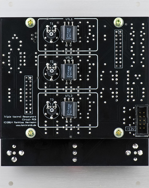
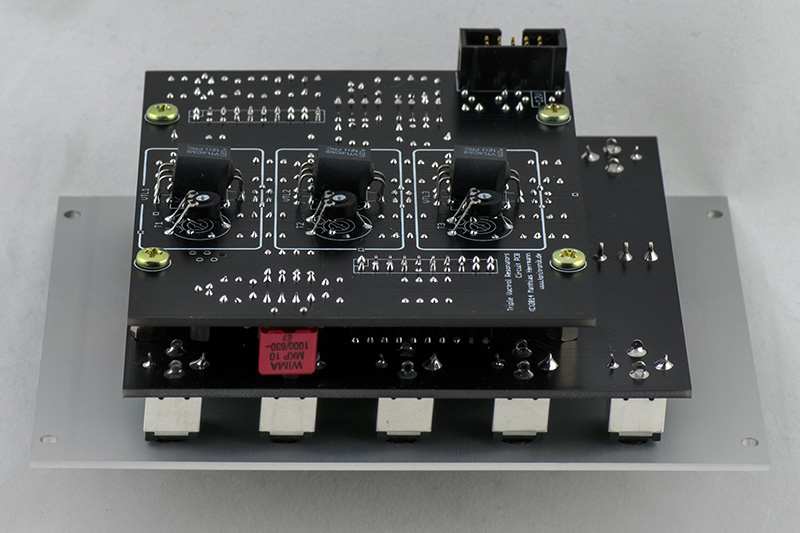
I used 12 mm standoffs between the two PCBs so I soldered the female header on the component side of the PCB, inserted the male header, spaced the boards together, and soldered the male header slightly off PCB so it would seat correctly. I soldered the 3.5mm jacks and potentiometers flush. I used serrated lock washers on all the potentiometers to make them coplanar with the jacks. I also used serrated lock washers on the two switches but mounted them to the front panel and then soldered them slightly off the board so they would be coplanar.
Operation
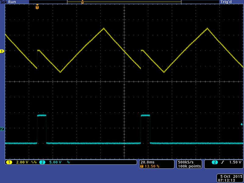
My first test was to verify there was an LFO output and I could sync it. I did note that in both ranges the LFO amplitude drops off quite a bit at the extreme CCW end of the LFO Speed control. This image shows the LFO sync to an external pulse.
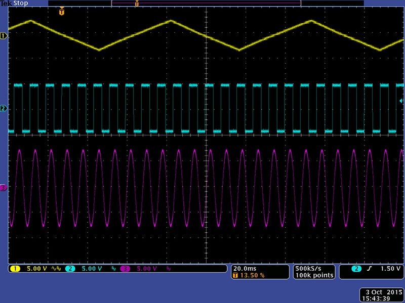
Next I verified each channel with no CV. This image shows a nice sine wave output at the center frequency of the filter.
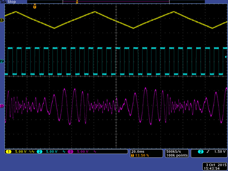
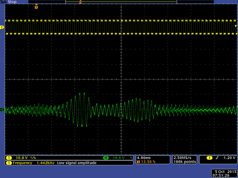
This image shows nice filtering with the LFO CV.
This image shows individual outputs when sweeping the filter with the LFO with a single square wave input into the All In jack.
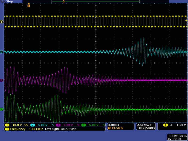
This image shows Sum Out when sweeping the filter with the LFO with a single square wave input into the All In jack.
Calibration
I could find no trimming instructions for this module. I ended up adjusting the trimmers with no external CV and the Frequency controls set to center, and a sine wave input. I manually swept the sine wave looking for the maximum which indicated the center frequency. I set channel 1 to the maximum of 2800 Hz which gave a range of 400 Hz to over 9 KHz. I chose 60 Hz for the low frequency cutoff for channel 3 which gave a mid-position frequency of 700 Hz. I chose 1000 Hz for the center frequency for channel 2. This gives a nice spread with lots of range in the Frequency control as can be seen in the following table.
| CCW | Center | CW | |
| F1 | 400 Hz | 2800 Hz | >9000 Hz |
| F2 | 120 Hz | 1000 Hz | 6500 Hz |
| F3 | 60 Hz | 700 Hz | 5000 Hz |
The second unit I built had one channel that was weak and thin. On the scope the waveforms were much lower in amplitude and not as well shaped. I ended up swapping out that channel's vactrol which fixed the issue. When I measured the resistance of the one I removed with the one I replaced it with at a fixed voltage and current the original measured several thousand ohms while the replacement measured several hundred ohms. As to be expected there was variability between the two units based on the vactrol tolerance. I tuned F2 and F3 to the same center frequency and F1 was tuned full CCW. I believe the importance is not the exact range but that the channels have some difference between them.
| CCW | Center | CW | |
| F1 | 63 Hz | 630 Hz | 3500 Hz |
| F2 | 100 Hz | 1000 Hz | 5800 Hz |
| F3 | 13 Hz | 700 Hz | 7000 Hz |