|
292M-B Quad
Lopass Gate |
|
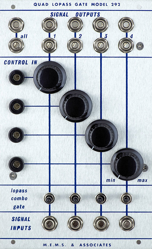
The 292M Quad Lopass Gate is the B version which uses hardwired switches instead of CMOS switches so does not include the remote capability. This module also has the M.E.M.S & Associates panel.
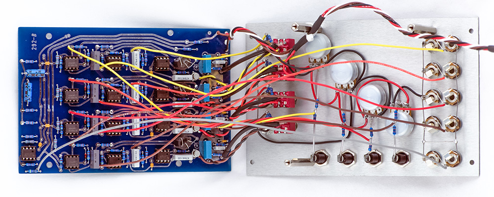
The original used terminal strips for power and the CV resistor but I decided this was unnecessary. The potentiometers have +15 and Ground and their terminals can be used to distribute these wires. -15 is only used on the PCB so can simply connect there. The resistors are sufficiently rigid to allow connections of the various wires.
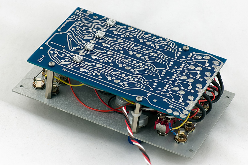
Only three standoffs are used for the PCB as the All Out jacks interfere with the fourth. Also note that the lower right standoff has been notched to fit around the film capacitors I used. There is also minimal clearance for the banana nut near that standoff.
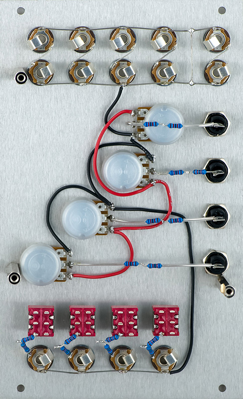
I chose to use dual vactrols as all 8 should be matched. I wanted to use Excelitis and it would be quite a challenge to find 8 matched vactrols. By using duals I had to only match 4. The original used mostly ceramic disc capacitors and I upgraded to film.
I used coax for the grounded shield and twisted pair for the non-grounded shield.
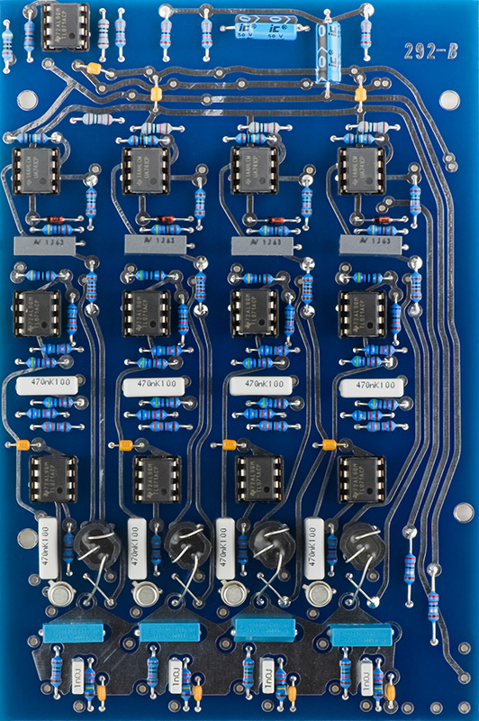
The rear of the PCB has the 1 nF capacitors which were added later.
The 292B schematic is a fairly poor copy. I cleaned i up quite a bit. The schematic shows a DPDT switch for filter or gate and of course later 292C has a middle position for Combo or Both. I don't know what was on the original 292B but this design will work with a center off switch for Combo. One difference is the gain is increased in the 292C only for Gate. In this design, the gain is reduced for Filter which increases the gain in Combo which can be seen in the scope photos below.
Operation
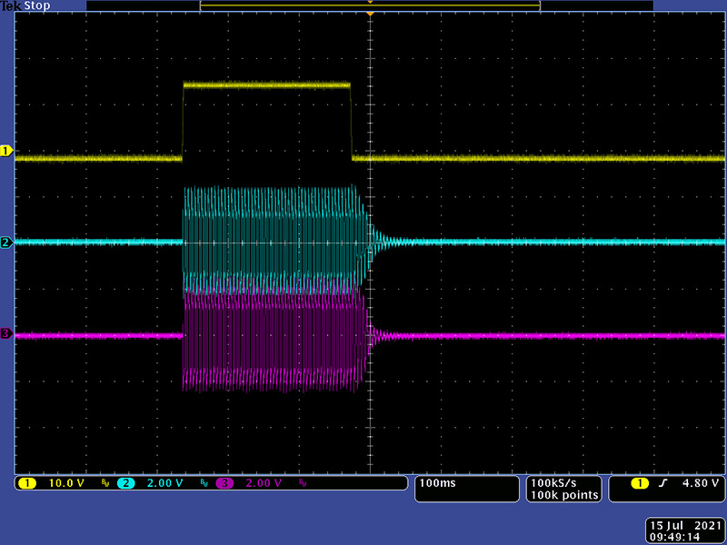
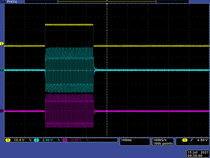
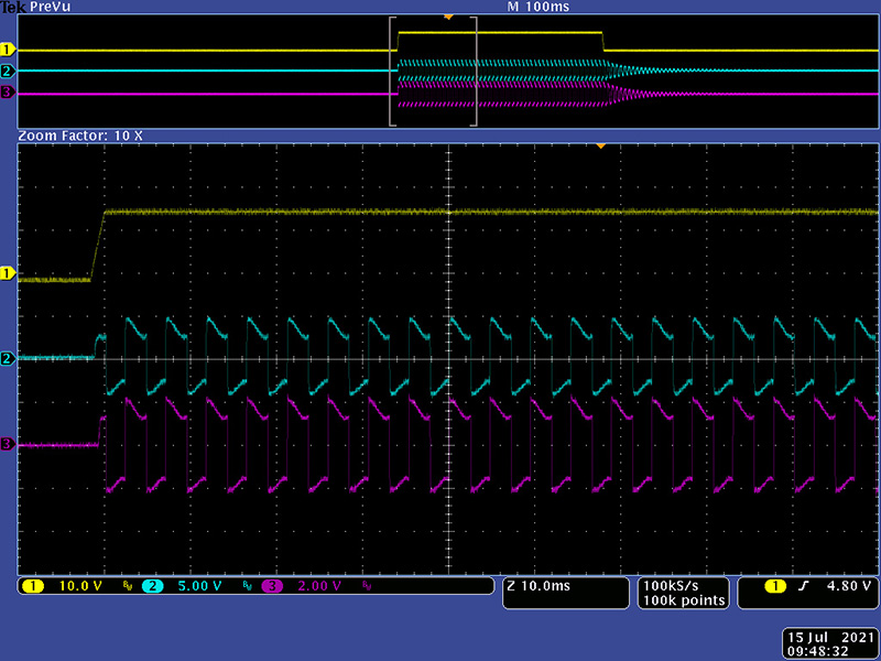
I setup both my 292B and my 292C module for comparison. Since they are similar in the design of the core I expected they would perform about the same with the exception of the level difference on the 292B in combo mode as mentioned above. I drove them with my 284 with minimal attack and decay. With the 15V output this will drive directly the 292B but will over-drive the 292C. This image shows the Lopass mode. You can see the vactrol decay on both.
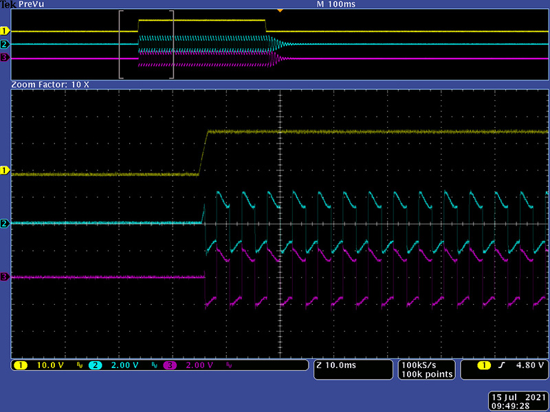
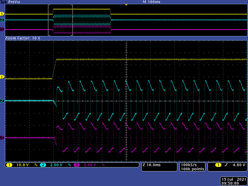
This image is the zoomed view for the rising CV edge for Lopass mode.
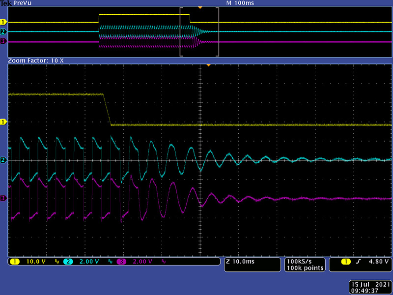
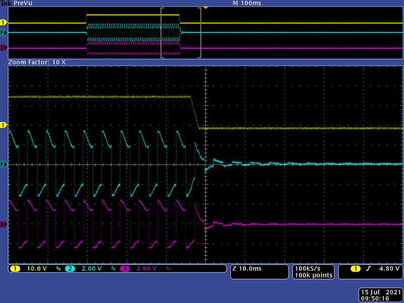
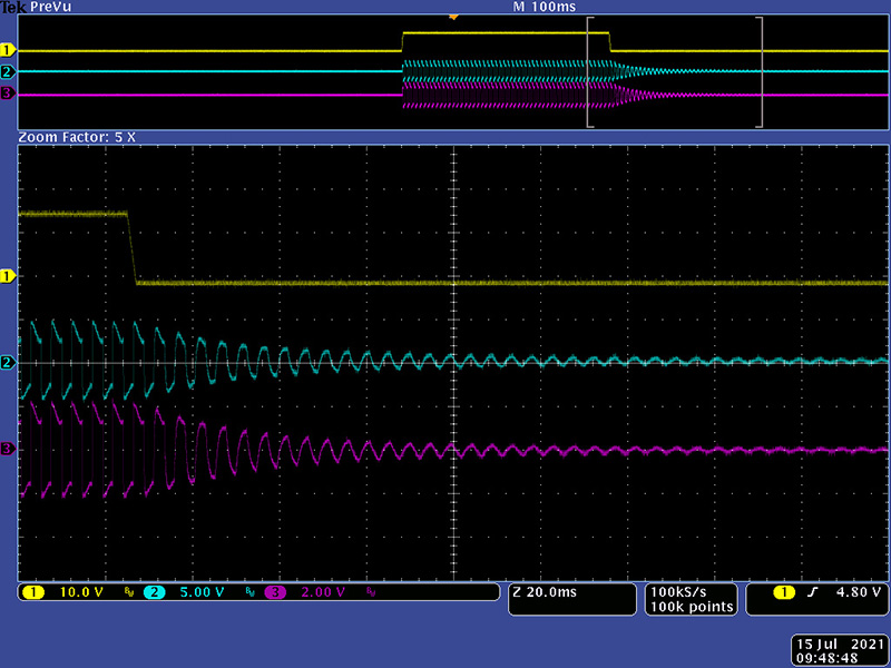
This image is the zoomed view for the falling CV edge for Lopass mode.
This image shows the Gate mode.
This image is the zoomed view for the rising CV edge for Gate mode.
This image is the zoomed view for the falling CV edge for Gate mode.
This image shows the Combo mode. You can see the a more pronounced vactrol decay on both. Also note the scale of the 292B is increased since the amplitude in Combo is greater.
This image is the zoomed view for the rising CV edge for Combo mode.
This image is the zoomed view for the falling CV edge for Combo mode.
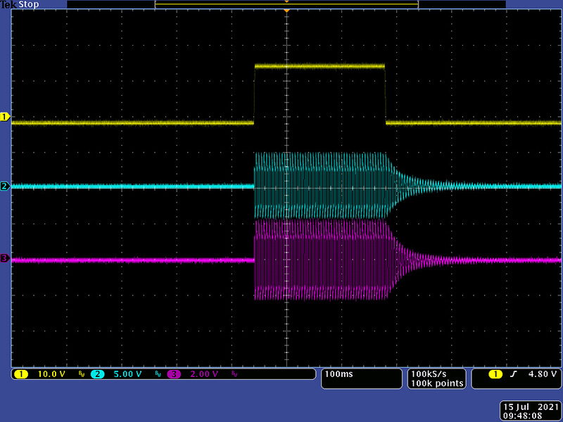
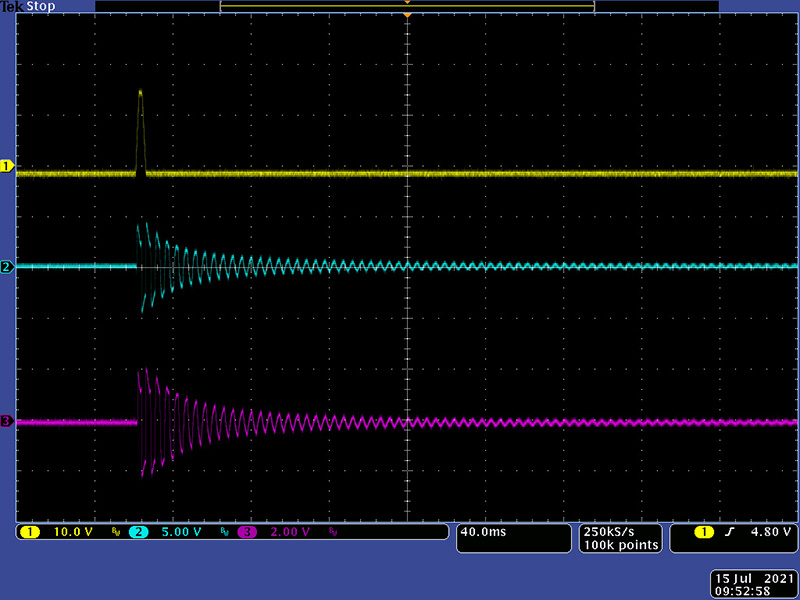
This image shows the Combo mode with a short pulse.
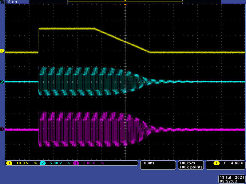
This image shows the Combo mode with some decay to accentuate the vactrol decay.
As expected, they perform similarly.
Design
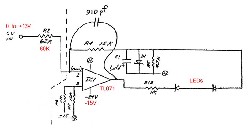
One of the interesting points of this design is the use of 0/-24V to power IC1 for the vactrol control loop circuitry. The 741 has a minimum supply requirement of +/-4.5V although the minimum recommended is +/-10V. Don could have chosen -/-24V to meet this recommended range. Mine works fine using 0/-15V.
Another oddity is the op-amp is biased at +0.15V which is above the positive rail although in practice is biased just a bit negative.
I breadboarded this control circuit and drove it from a 13V unipolar triangle wave at 1 Hz to better understand the vactrol current. I used red LEDs and a TL071 powered from 0/-15V for this investigation. I reduced the input resistor slightly to give me a comparable CV range of 0 to +13.5V.
This scope image shows my triangle CV (yellow) and the voltages on each side of R13 (cyan and magenta). The red is the resultant voltage across R13 by subtracting these two voltages. Since R13 is 1K and the scale is 1V/Div you can read the red trace directly as 1 mA/Div of vactrol current.
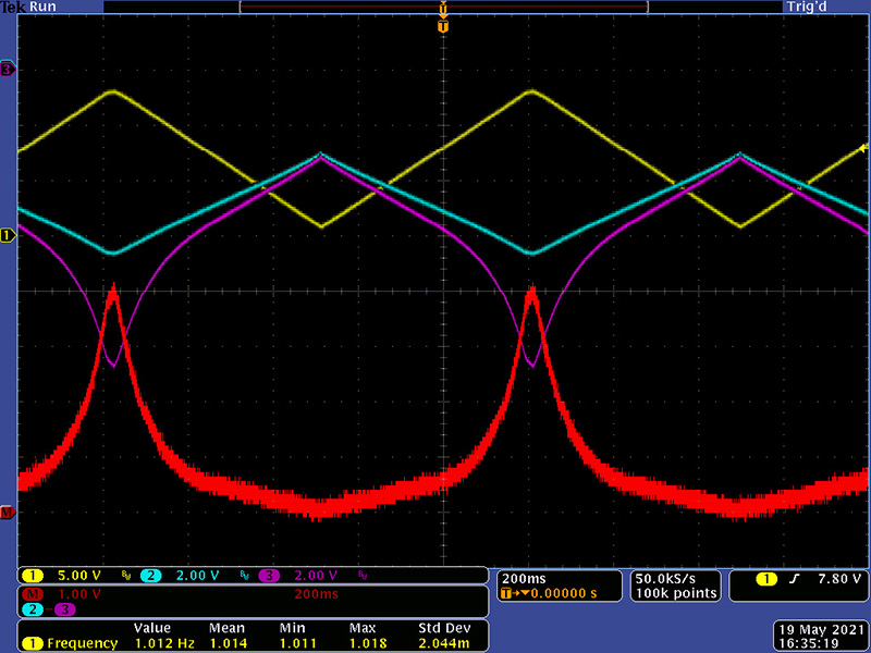
The 3.9V zener puts a knee in the response curve. 0 to +8.5V of CV is fairly linear at 75 µA/V. At 8.5V the current increases more sharply and from 8.5V to 11V increases to 360 µA/V. Above 11V the current increases to 1.25mV/V.
If you increase the CV frequency to 100 Hz then C1 adds some short duration discontinuities.
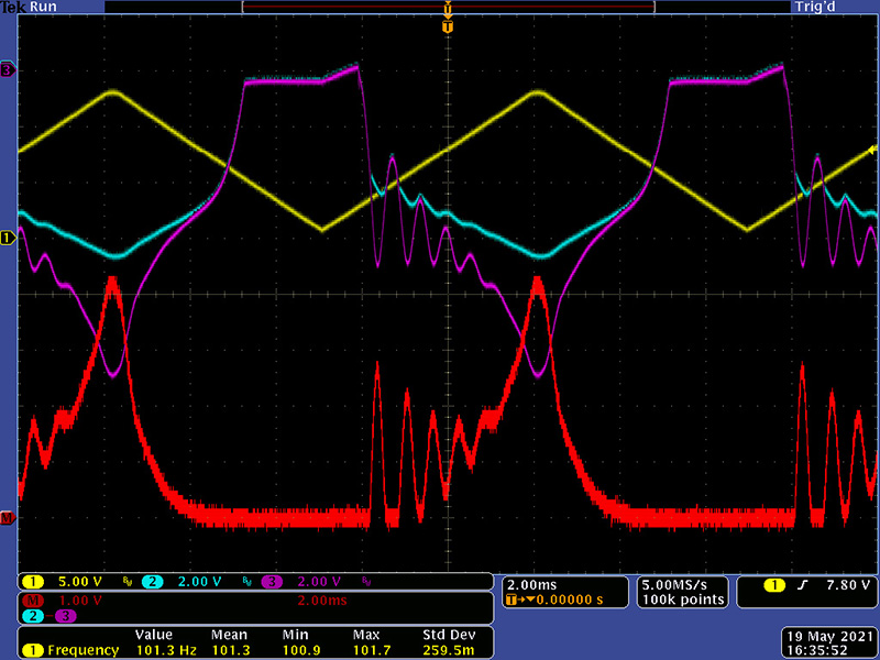
These discontinuities are only 400 µS wide. For the Lopass Gate you want vactrols with a longer decay tail so would not respond to these short perturbations. I did not repeat these measurements on the actual module.