296M Programmable Spectral 
Processor Low Profile Investigation

This page documents my initial build investigation to reduce the depth of the 296m to less than 3". Since this build the motherboard PCB has been revised to eliminate the interference between the rear mounted resistors and the card connectors. I have also revised and simplified my approach to installing the pins without the headers and the use of Alps 9mm potentiometers. This page is retained for reference information only.


Low Profile Construction

I made a second 296 with the initial MEMS PCBs to investigate lowering the profile to fit a 3" boat. I found that removing the plastic headers from the male pins and using 14 mm standoffs was a reasonable solution. This also requires cutting some plastic pieces from the female headers and mounting some resistors on the motherboard in piggyback.


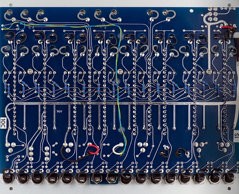
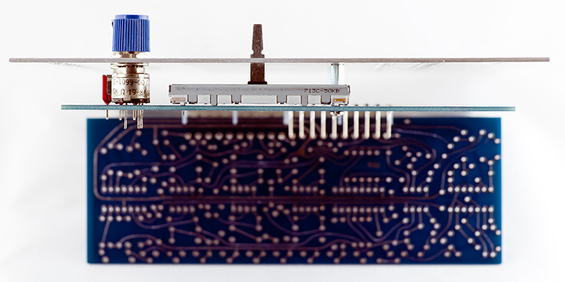
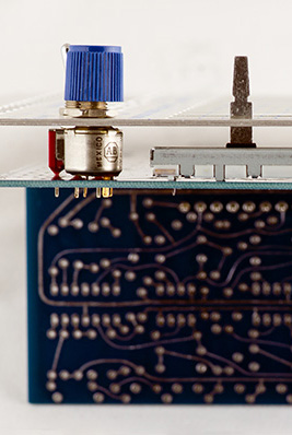
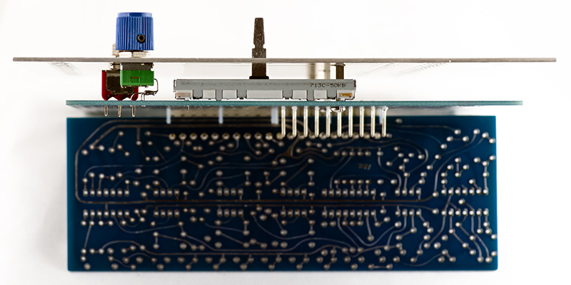
Low Profile Modifications

There are two areas to reduce depth of the module: reducing the height of the front panel spacers and removing the plastic headers from the motherboard pins. While the switches will fit with 12 mm standoffs the PRV6 style potentiometers may not so you will have to check. Reducing the spacers by 3 mm is insufficient to fit a 3" deep boat.

The most practical method is to eliminate the plastic headers which saves 0.125" and is the space savings needed. The Molex female connector without the plastic male header provides about 0.080" clearance between the card and motherboard which is ample for most leads and wires but interferes with some of the 33K resistors, wires, and banana jacks.


I found this the best method for a new PCB build. You can do this after axial components are installed but before the sliders, switches, and potentiometers are installed:

The Molex pins (Mouser 538-26-20-2101) are 0.045" diameter and while other individual loose pins are available, they are extremely expensive. The only reasonable cost option is to use the pins from the 538-26-20-2101 Molex headers. Use pliers on the bottom (solder) side of the plastic header and pull the pins individually through the header to remove. The pliers will leave marks on the pins so keep them organized so you know which is the "clean" end. Insert the good end into a Molex 0009481104 female connector (Mouser 538-09-48-1104) and push them through so they extend beyond the header.

Once 10 are installed, then press the female connector against a flat surface on the opposite side so the pins are aligned flush with the top of the connector. There is some slop in this connector so align each pin to be perpendicular and centered. 

Carefully insert this from the rear and solder the pins on the front. You can see the pin alignment in the hole so make sure they are all centered before soldering. The connector will push flat against the PCB making sure they will be aligned vertically perpendicular to the PCB. After soldering, cut the pins off flush with the PCB and then quickly resolder making sure the hole is completely filled. Pull the female connector off and realign any pin that is not vertical. I would not use this female connector on a card since it has been subjected to the heat of soldering 198 pins.

This photo shows the pin alignment using this method. While the pins all fit the connector there are a couple that could be straightened. Most of the pins have a lower solder profile on the rear. My pins measured 0.448" in height.

The vertical alignment is quite good.


If you have machine tools available you can use this method:

Mill the plastic header down to 0.2" width. This can be installed from the front and soldered on the rear and will fit between the sliders. If you mill too narrow the header will fall apart. Since you will be soldering on the rear connector side so be sure to not wick solder up the pins.

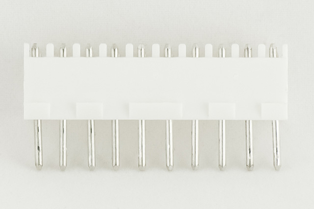
A variation of this method is to pull the plastic header instead of machining it narrower:

Insert the header from the front and solder on the rear. Be sure to not wick solder up the pins. Use hot air to heat up the plastic header. Use pliers across the narrow portion of the plastic header and rock it back and forth with a pulling motion to pull it up just a bit. Work your way down the header and repeat until you get the plastic header away from the PCB. You may have to reheat it. Eventually it will pull off easily. Cut the pins flush to the PCB.

This photo shows the pins alignment and the solder fillet from soldering on the rear of the PCB. My pins measured 0.387" in height.

The vertical alignment is quite good.


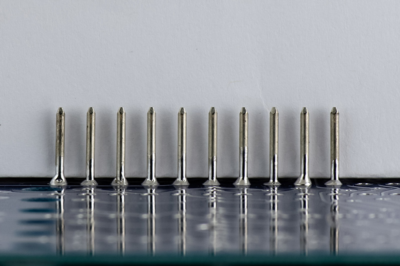
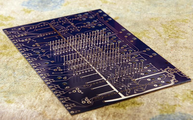
 Here's half of the pins inserted. It is slow but steady work.


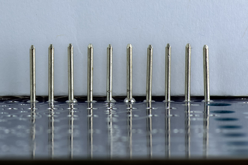
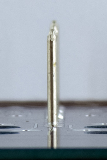
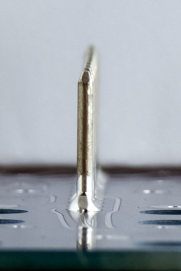
An individual contacted me on their method for eliminating the plastic header. They pressed the plastic header down flush with the bottom of the pins. They inverted the board and installed the pins partially through the PCB. It turns out that a 5.5 mm spacer provides the right spacing so the pins do not extend through the card connectors. They simply tack soldered the end pins, removed the spacers, soldered and cut the pins. This photo shows the header spaced with 5.5mm standoffs on both sides (4 standoffs) prior to tack soldering. This is an easier solution. This image shows four 5.5mm standoffs used as spacers.


If your motherboard is already assembled, then this is likely the only method.

Use hot air to heat up the plastic header. Use pliers across the narrow portion of the plastic header and rock it back and forth with a pulling motion to pull it up just a bit. Work your way down the plastic header and repeat until you get it away from the PCB. You may have to reheat it. Eventually it will pull off easily. You will need to cut the pins off at the appropriate height so they don't protrude through the female connector. Although the pin height above the header is 0.45", only 0.37" is needed to fully contact the female connector. The header is 0.125" thick. Cut the pins off to 0.25" above the header (cutting off 0.2"). After cutting the pins you will need to sand the sharp edges so they do not scrape the mating connector.


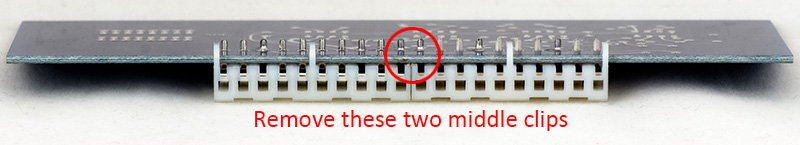
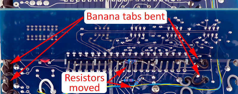
Without the headers the female connectors on the cards slightly interfere with many of the 33K resistors which are close to the rear of the cards. You need to trim off the two plastic tabs between pins 10 and 11 on all cards.

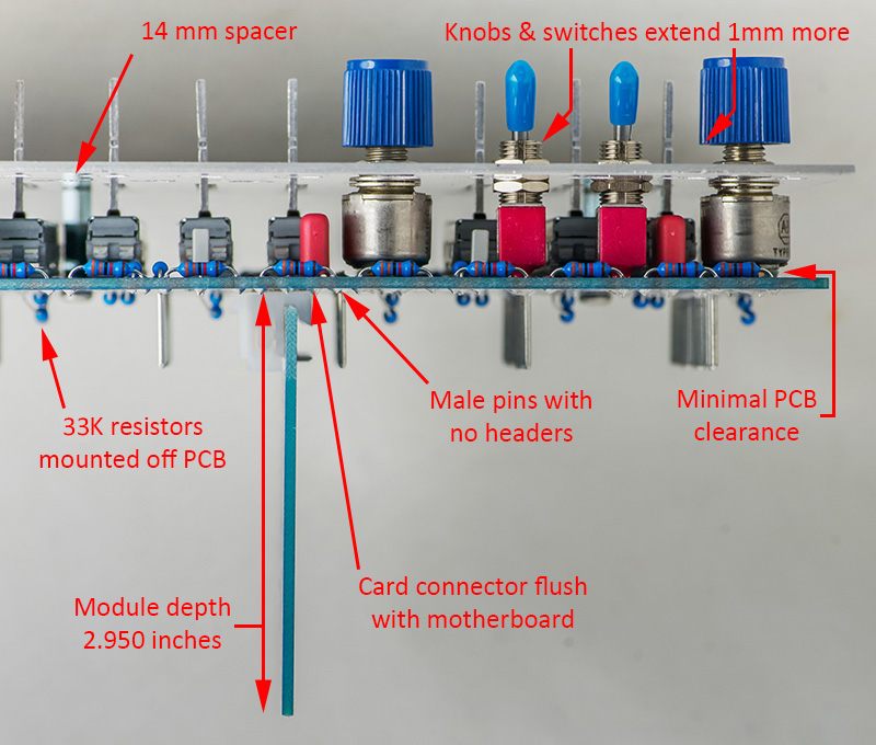
10 of the 33K resistors will slightly interfere with the bottom of the card edge. This doesn't allow the card to be fully seated, but it is sufficient to fit into a 3" deep case using the shorter standoffs (below). To allow full clearance, five of the 33K resistors can be rotated and one lead soldered to a trace and 5 of the resistors need to be lifted and mounted on top of the 22K resistors. Six of the resistors are fine as-is.

Another possibility is to use smaller diameter resistors, 1/8W or Mouser 660-CFS1/4CT52R333J,  which should provide ample clearance.  (untested).

Larger photo of resistors


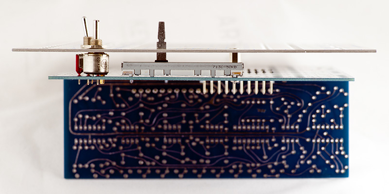
Removing the plastic header will reduce the depth to 2.96". The card edges will likely touch the bottom of the boat so make sure there are no screw heads or any other protrusions which could contact the cards or traces. To gain some additional clearance the standoffs height can be shortened.


For PRV6 style potentiometers more than 12 mm:

The datasheet doesn't show the dimensions for the PRV6 potentiometers from the rear to the mounting flange. I did not use the 72-PRV6-50K called out in the BOM so I couldn't measure them.  I do have some of this style potentiometer and it has folded over tabs at the base which can short to PCB traces. These measure 12.42 mm so will not fit with 12 mm standoffs  A 14 mm standoff (Mouser 761-M1261-3005-S-12) is available and expensive, but only three are required. A round nylon 14 mm post is half the cost (Mouser 761-M0513-3-N). Using 14 mm will provide ~0.040" clearance between the cards and boat. I like this alternative best as it provides some clearance and the controls fit closer to the panel.

With 14 mm standoffs and no header on the pins, the cards now touch the banana solder tabs. You can bend them out of the way (I bent towards the bottom) and make sure the wire comes off the side of the tab and not the top. This photo shows the moved 33K resistors and the bent banana solder tabs.


Not Recommended
For PRV6 style potentiometers less than 12 mm deep:

You can use 12 mm standoffs which provide ~0.120" clearance between the cards and boat. I have some PRV6 style potentiometers that do not have folded over tabs and are 11.7 mm deep. This is very close so check your spacing to ensure no traces are shorted. However, this increases the issue of the banana solder tabs interfering with the cards which I did not investigate further.

I do not like the appearance of 12 mm spacers as the controls, sliders, and potentiometers extend through the panel more and the knobs sit higher.


 Substituting 9mm Alpha potentiometers:

You can use 12 mm standoffs with Alpha 9 mm potentiometers. Cut off the four tabs on the bottom and the locating pin as close as possible. Fold the narrow portion of the leads and solder short solid wire to the leads. Bend these to fit into the PCB. This obviously is a more difficult assembly of the panel with 5 potentiometers. You need to use care to make sure you don't spin the potentiometer when tightening the panel. This also has a significant cost savings. The original used 25K linear potentiometers so you can buy the correct value. However, this increases the issue of the banana solder tabs interfering with the cards which I did not investigate further.


With the shorter standoffs the cards will interfere with the banana jack solder tabs. You can bend these towards the bottom and make sure the wires come off from the side of the tab and not the top.


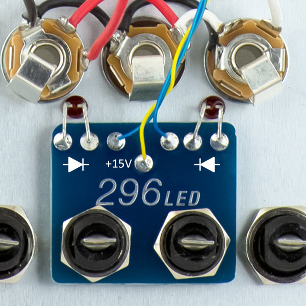
The initial batch of LED boards also had the orientation of the LED backwards. This closeup shows the correct orientation.


back