 |
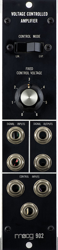
Moog 902 Voltage Controlled Amplifier |
|
The Moog 902 Voltage Controlled Amplifier has both linear and exponential response. The two inputs are differential and are normalled to ground. The lower input jack is subtracted from the upper input jack, not added. The two outputs are differential and the upper output is inverted. So to keep the phase of a single input the same you would use opposing jacks - upper input and lower output. This is a later revision from the three cabinet Moog and the panel has the new logo and module number located at the bottom.
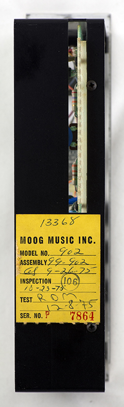
This module was assembled in September and tested in December of 1975.
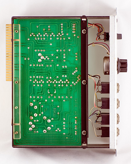
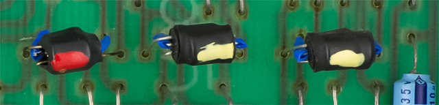
This module no longer has the separate edge finger PCB. Matched transistors carry an identifying stripe: yellow for NPN and red for PNP.
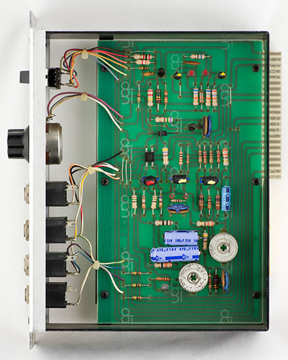
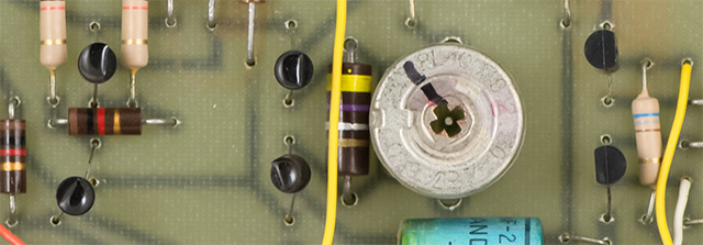
Moog improved the operation of the voltage controlled amplifier by matching transistors both electrically and thermally. The top image is the three differential pairs from the earlier revision. They are isolated thermally and there is no indication of matching. The bottom image shows the transistors heat shrunk together and then identified with a the same stripe: yellow for NPN and red for PNP.
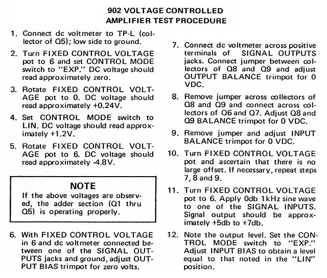
Calibration
This module exactly matches the schematics and behaved well which made trimming much easier. I found it didn't make much sense to do step #6 before #7-8-9 sequence as you had to repeat step #6 afterwards.
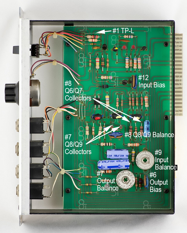
Here are the locations of the trimmers and collectors along with their calibration step.
Operation
There is a scope image of the voltage controlled amplifier operation on the three cabinet Moog 902 page.