|
Moog 901A Oscillator Driver |
|
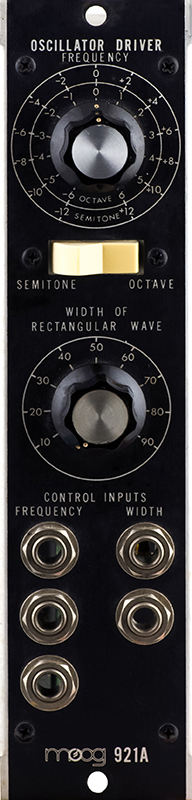
The Moog 921A Oscillator Driver provides the control voltage, and the pulse reference voltage for the 921B Oscillator. It contains a control voltage summer and a switched frequency control for either semitone or octave. Module cabling is wired in parallel so that a single 921A can control up to three 921B modules.
The gain of the module is 0.5X so it outputs 0.5V per octave. Why 0.5V? The module is powered of +12V and -6V so the op amps can only drive to less than -6 volts. This module needs a range of +/-3V for the frequency control plus whatever voltages are added from the CV jacks. I suspect they simply reduced the gain to have adequate headroom with the restricted negative supply voltage.
The 921A Oscillator Driver is a very simple 1 MU wide module. One of the trimmers has been replaced on this module.
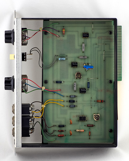
I added the resistor seen in the top right corner of the PCB. The three trimmers are for gain (0.5X), frequency control range (6V) and offset so the frequency control is +/-3V. However, 0V ends up wherever the resistance of the potentiometer is half and not necessarily centered. The calibration instructions say to rotate the knob until 0V lines up with 0 on the scale. I chose to instead slightly change the taper of the potentiometer so 0 was exactly centered. Thus the knob is accurate at -6, 0 and +6 and some of the intermediate settings are slightly off. This made more sense to me than not having the knob align with the panel graphics.

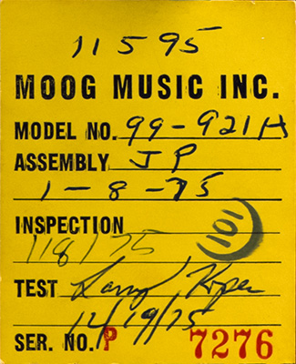
The rear serial number label format changed by 1975. This label indicates the module was assembled Jan. 8, 1975 but not tested until Dec. 19, 1975. Was it really in the queue for almost a year? The date codes on the three ICs are the 15th, 19th, and 27th week of 1974.