 |
Moog 960 Sequential Controller |
|
The 960 Sequential Controller has three PCBs. PCB1 is the main sequencer logic designed around a flip-flop shift register and control logic. PCB2 is the LFO designed using a unijunction transistor (you never see these anymore), LFO ramp to pulse conversion, output voltage level circuitry, and the LFO on/off and step control. PCB3 is the LFO voltage control circuitry. The column Outs are driven from the RTL so they are +3.6 volt V-Triggers.

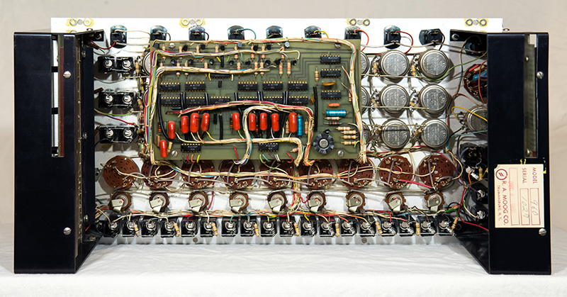
Hi-res image of the 960 Sequential Controller back
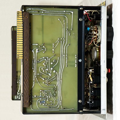
PCB-2 is mounted on the right side components facing out.
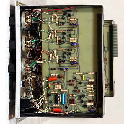
PCB-3 is mounted on the left side, components facing in.
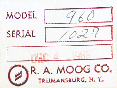
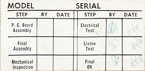
The serial number label indicates a Dec 4, 1968 date code. Moog did not give modules serial numbers until 1967 and started at serial 1001 so this is the 27th 960 produced after assigning serial numbers.
The test label indicates an Apr 9, 1971 date code but the ICs all have a 1968 date code.
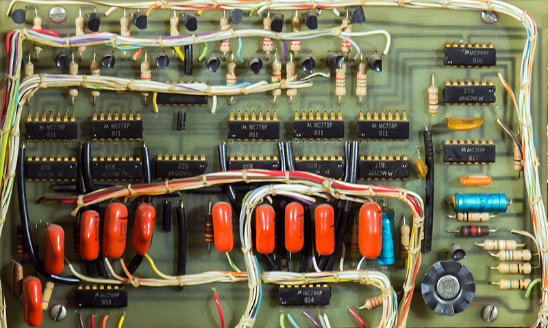
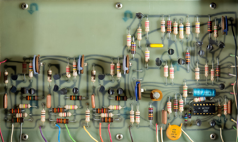
PCB-1 is the main sequencer logic which is comprised of the MC700 series RTL and the +3.6V supply. The standoff supports short to runs on the back of the PCB and need to be insulated. This PCB has red tape around each of the four mounting screw insulating the traces.
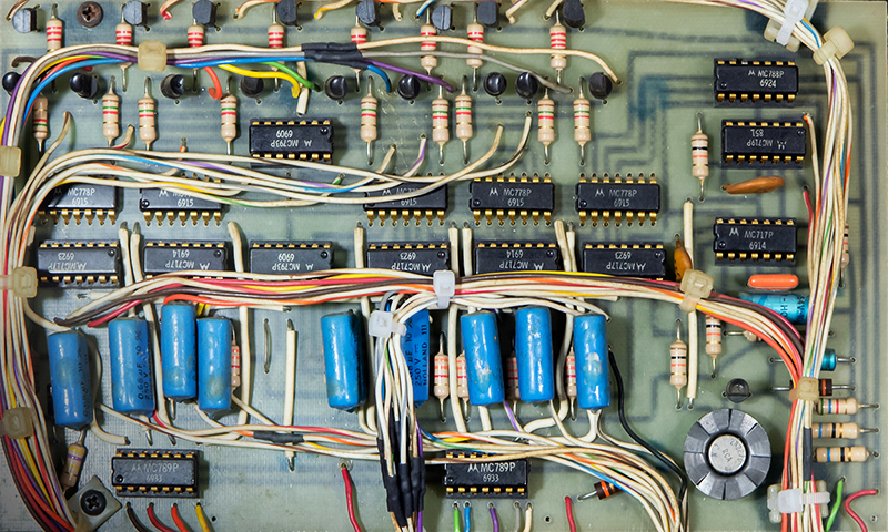
This later PCB-1 (1969 IC date code) has some changed circuitry in the lower right corner and wire-tie pads added on three of the mounting screws. For some reason a number of the wires to this PCB had been cut and required splicing (all the black heat shrink).
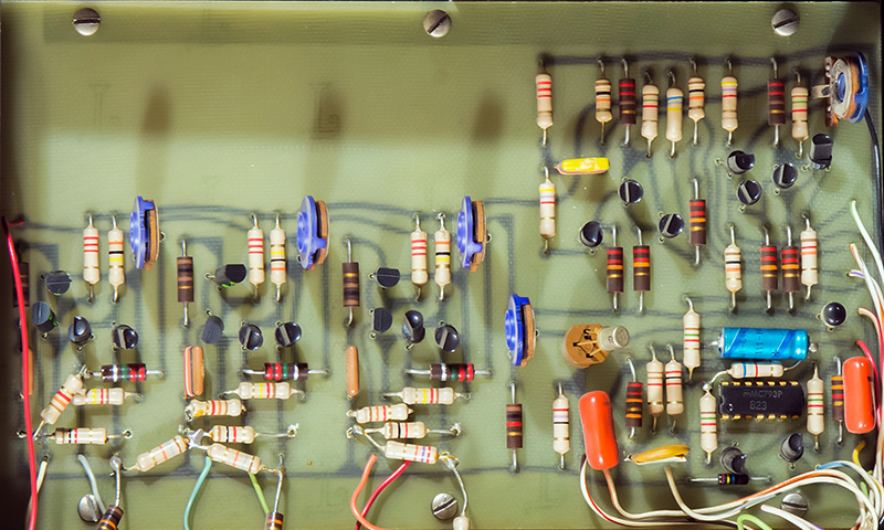
PCB-2 is the LFO, pulse-shaping and control circuitry, and the output voltage level circuitry. There are some flying resistors in the lower left corner of the PCB. The unijunction transistor is in the socket.
This later PCB-2 (1969 IC date code) incorporates the flying resistors onto the PCB.
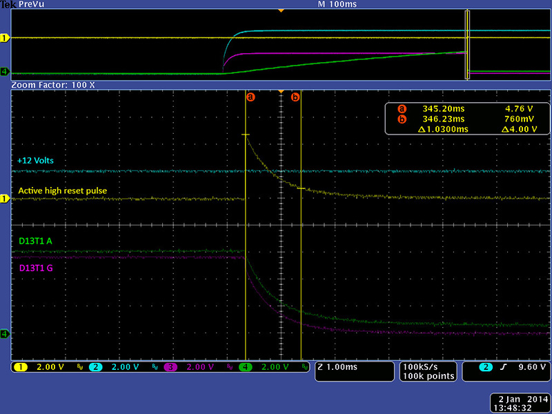
I thought one of the power-on-reset circuits was inoperative as the 960 would power up with random columns set. I characterized the functional power-on reset which was a 1 mS positive true signal. I was surprised to find that the earlier 960 has no power-on reset circuit. This was a modification that was added later on PCB3. You have to press a set button to initialize the earlier 960.
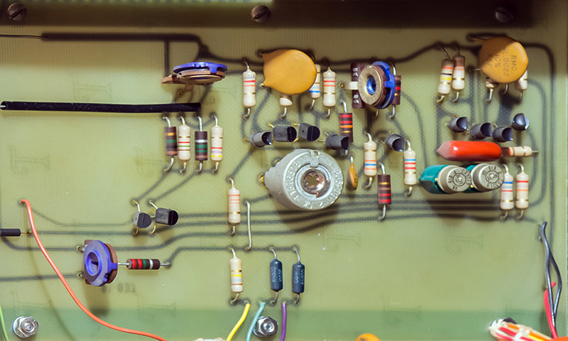
PCB-3 is the LFO voltage control circuitry and is pretty sparse.
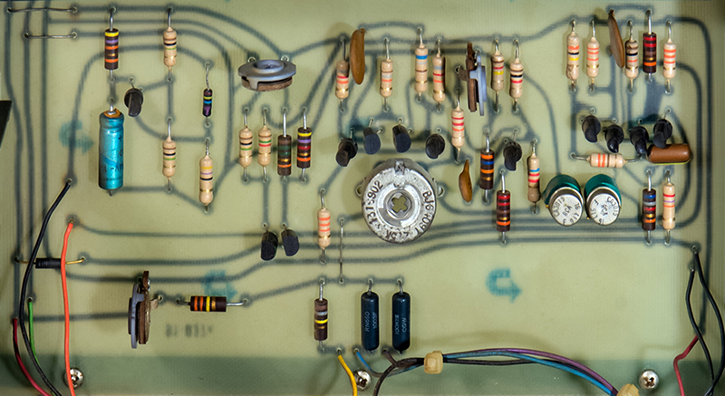
This later PCB-3 (1969 IC date code) has the power-on reset circuitry added on the left side.
Operation
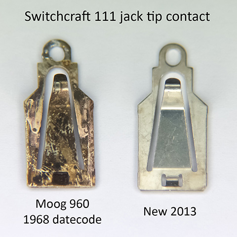
As usual with a 45 year old product the first part of restoration is determining what modifications have been made over the years and removing them. A number of lamps were burned out and needed to be replaced. Next was to verify the one-shot multivibrators designed with RTL gates. Several of them had changed timing considerably such that the the sequencer was inoperative. The capacitor values had not drifted so I can only assume the RTL electrical characteristics drifted over time. I paralleled capacitors on the rear of the PCB until I had the proper width pulses which restored operation. Some of the carbon composition resistors had drifted so I replaced them and recalibrate the circuits. The sequencer outputs does drift at power-up and requires a couple of minutes to stabilize. All the jacks on both sequencers were badly corroded and intermittent. They had surprisingly low insertion (and hence retention) force. I replaced them since the insertion force was so poor.
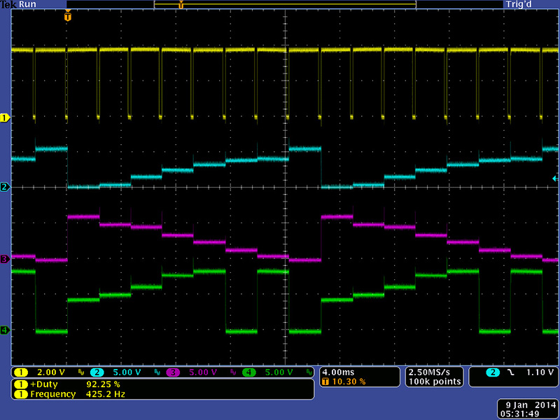
The maximum frequency of the 960 Sequential Controller is just a bit over 400 Hz. The clock is a positive 90% duty cycle and increases slightly at the maximum frequency. This image shows the three outputs.
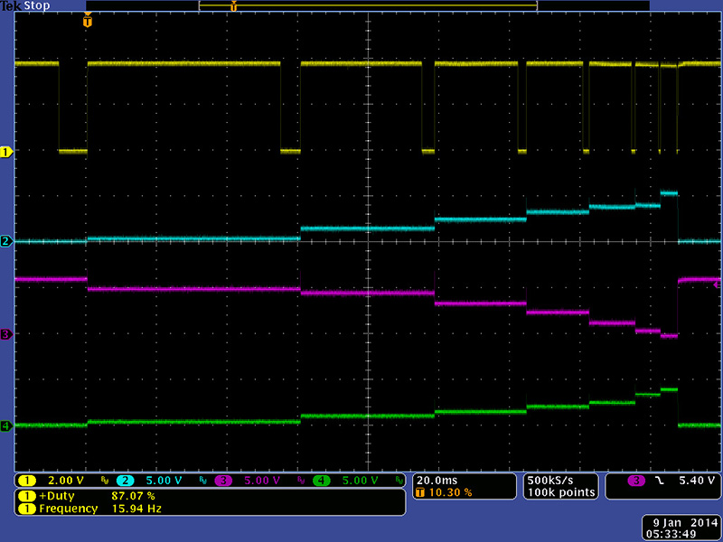
Row 3 can be switched to modulate the clock as seen in this scope image.
I was surprised to learn that I couldn't patch a column Out to a column In to create a shorter length sequence, say from column 3 to column 6. Any column set (from the pushbutton or In jack) resets all the flip-flops (well actually sets them since the outputs are inverted) and sets (well actually resets) the desired flip-flop which requires the set pulse be longer than the reset pulse to operate properly. In the case of patching a column Out back to an In, the reset clears the flip-flop so the Out goes false before the flip-flop for that column is set. Circuitry detects that no columns are set and sets column 1. The column Out pulse needs to be stretched which of course is what a 961 Sequencer Interface will do. I patched two 960 Sequential Controllers together to create a 16 step sequencer as shown in this video.