|
Moog Sonic Six Restoration |
|
I don't own a Sonic Six but restored one. The Sonic Six is is very different from other Moog synthesisers. It was based on the Sonic V which was designed by an ex-Moog employee for Musonics. In 1971 the R. A. Moog company and Musonics merged to form Moog/Musonics which later renamed to Moog Music Inc. The Musonic Sonic V was redesigned into a portable synthesizer to become the Sonic Six which was released in 1974. It certainly differs from all other Moogs in look and feel. I started a Sonic Six thread on Muffwigglers.
Retro Synth Ads has a nice page on the Sonic Six including a scan of a 1974 brochure.
GreatSynthesizers has a nice write-up on the Sonic Six.
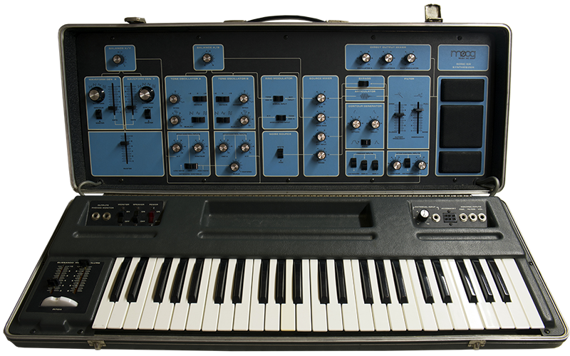
Hi-res photo of the Moog Sonic Six
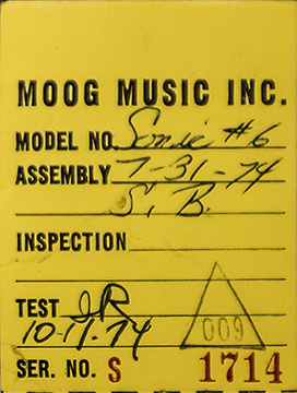
This Sonic Six was built in July of 1974 but wasn't tested for another 10 weeks. By 1974 the company was known as Moog Music Inc.
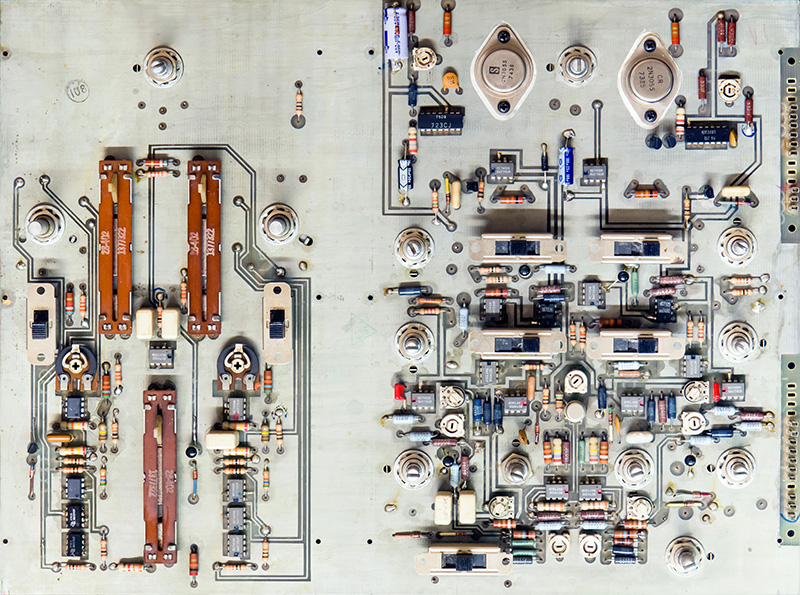
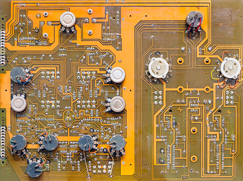
The top case consists of the majority of electronics on two PCBs. PCB1 is on the left and consists of the LFOs and VCOs. The component side is unmasked with a large ground plane.
The rear of PCB1 is masked and the potentiometer and rotary switches extend through.
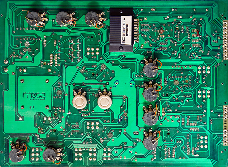
PCB2 is on the right and consists of the mixer, envelope generator, mixer, and amplifier. The component side is unmasked with a large ground plane.
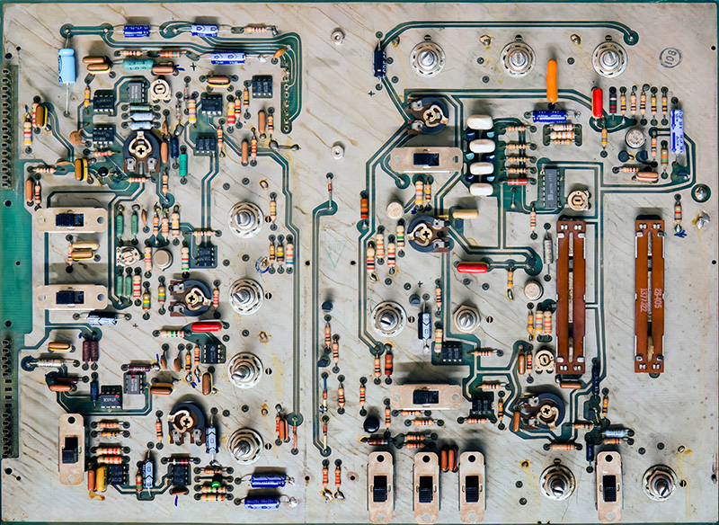
The rear of PCB2 is masked and the potentiometers extend through. The amplifier module is also mounted on the rear.
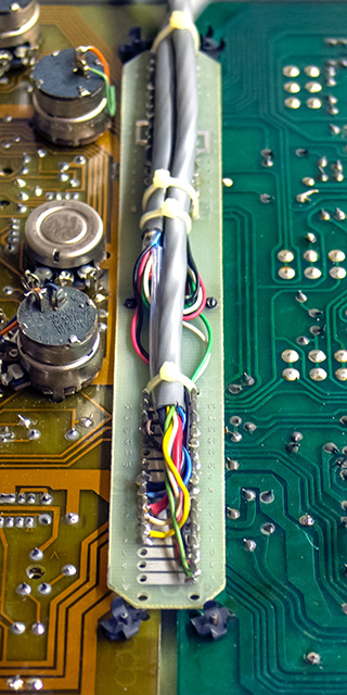
The PCBs connect together and with the cables through a thin PCB. The PCBs mount on small pins with press-fit retainer clips.
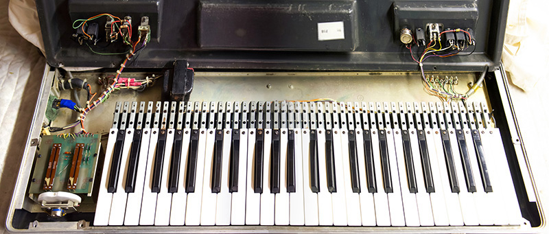
The bottom case consists of the power supply, keyboard, and miscellaneous front panel controls and connectors. The power switch operates on the unregulated DC voltage so the transformer, rectifiers, and capacitors are always powered on. I gave up trying to find a replacement power switch. It requires a completely separate 28 VDC lamp which is powered from the unregulated negative voltage. The power switch was intermittent so I disassembled it for repairs and added a 3 mm LED and series resistor in place of the lamp. It is not quite as bright but certainly will last a lot longer. Note this photo is a composite of a left and right side photo so the keyboard cover has some geometric distortion.
.
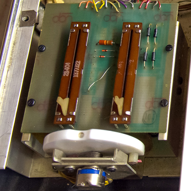
The large filter capacitors are mounted below PCB3 and the rectifiers are on the right of PCB3. This board is missing the op amp buffer shown on the schematic in the pitch wheel circuit to improve the center dead zone. The schematics show an October 73 date which is before the synthesizer was built so they must have used up an inventory of old stock.
Initially I was under whelmed by the Sonic Six. It was certainly of lower quality than other Moog products of the era. However, as I calibrated it I discovered that the oscillators are quite stable. The Concert setting is tuned to middle C and is reasonably pitch accurate. I also found that the patch routings were quite flexible and powerful. The external audio and VCO, VCF and VCA CV inputs are also quite nice and expand the capabilities of this synthesizer. After spending some time with this synthesizer I have grown quite fond of it but it had to go back to its owner.
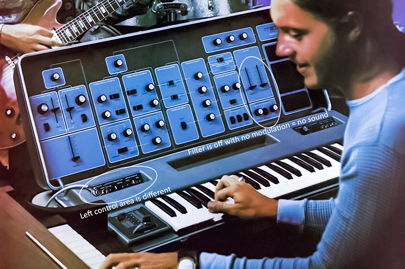
This image of the Sonic Six in a 1974 brochure shows a slightly different left control area with one less switch. The straight-thru mixer is turned off and the filter is turned down with no modulation inputs so there is no sound to worry about. But at least there is an audio cord plugged in.