 |
Synthesis Technology 5U E950 Circuit Bent VCO |
|
I wanted a 5U version of the E950 and so bought a full Eurorack module as Paul didn't seem to offer this module in the DIY version.
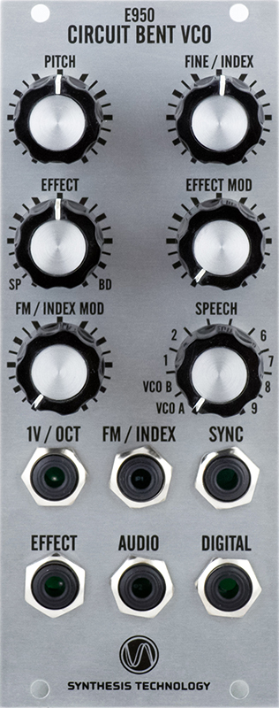
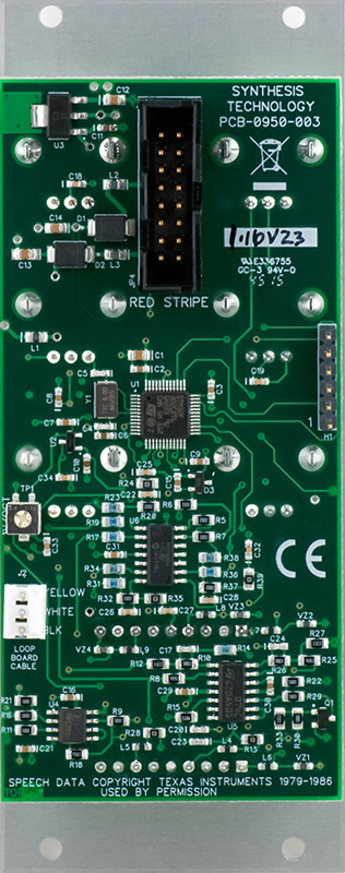
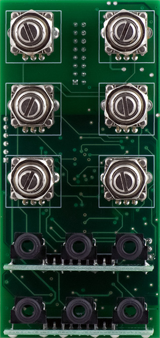
The potentiometers solder to the front of the PCB and the jacks solder to small daughter cards that also solder to the front of the PCB.
Construction
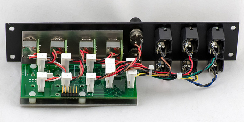
The Eurorack power, E951 Looping connector, and a 6 square pin connector solder to the rear. I removed all of the potentiometers and the two jack daughter boards and replaced them with 3 pin MTA connectors. I unsoldered and reversed the E951 Looping connector and the 6 square pin connector to the front of the PCB so I could mount the PCB on a bracket. There are no mounting holes so I drilled out all the potentiometer tab holes to 0.113" to accommodate a 4-40 screw and will use four as PCB mounting holes.
I removed the Eurorack power connector and replaced it with a Dotcom power connector which fits the same grid size. I removed pins 3 (+5V) and 6 (n/c) from the connector since the module only uses +/- 12V. This module will run on +/-15V with no changes and the Dotcom connector is still polarized with these missing pins.
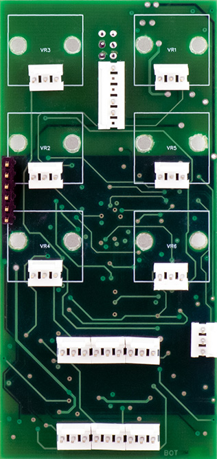
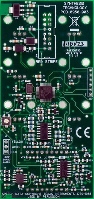
I wanted my E950 to fit in 1U so I used small knobs for the four main controls and tiny knobs (Mouser 506-PKG40B1/8) for the input attenuators. I used these tiny knobs in my CGS-35 Steiner VCF and they work quite well.
I decided to dual label this panel using colors to differentiate between VCO and Speech and I changed a number of labels to better match 5U modules. I had to design the Mode control special since it has 12 tic marks (polar coordinates in FrontPanelExpress works well for this).
I chose to build a temporary panel for this module. Note the image is an actual photograph of a panel made by gluing a laser print of the FPE design to an aluminum panel and lightly coating with lacquer.

1U E950 FrontPanelExpress design file
