 |
YuSynth |
|
I built this module around Yves Usson's Fixed Filter Bank as discussed on the Electro-Music forum. I love this filter just for the even and odd outputs. It really creates a nice stereo image that enhances the sound, especially through headphones. It was worth building it just for that (I can envision a simplified controlless module just for that purpose). The filter works very well to polish off the sound at various frequencies.
I purchased a PCB from Yves and made just minor changes to the build consisting of
Fixed Filter Bank schematic with mods (schematic used with permission by Yves Usson)
I did a quick patch of two sequencers and ran them through the FFB with even and odd outputs feeding the left and right channels. All controls are at their maximum so this just demonstrates the separation between outputs. I start in bypass mode and then switch to the filter mode, then toggle back and forth a few more times. Best listened to with headphones.
I installed the capacitors in groups of 8 using tape across them to maintain alignment while soldering. I was also able to redrill the PCB to fit a MOTM style 0.156" MTA four pin power connector.
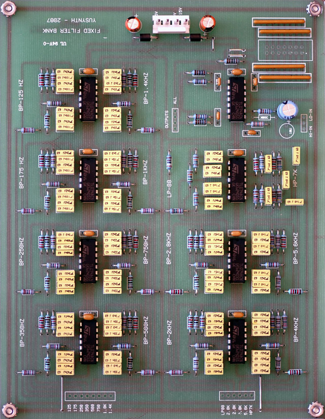
I used 100K linear potentiometers since I had access to some nice surplus Clarostat controls. The 50K input impedance to the inverting amplifiers makes the 100K controls feel more like a semi-log. Here's a plot of the voltage vs. rotation contour.
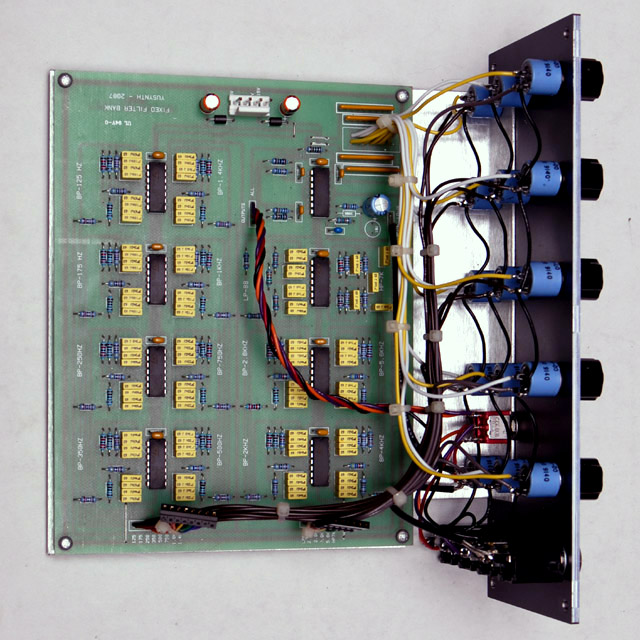
I adjusted the gain of the input stage to 1.5X to give a nice balance between normal and bypass operation. Wiring this up the front panel was a lot of work! I added extra 0.1" wire connectors on the outputs of all the filter banks to allow an easier path to expand this module if I choose to in the future.
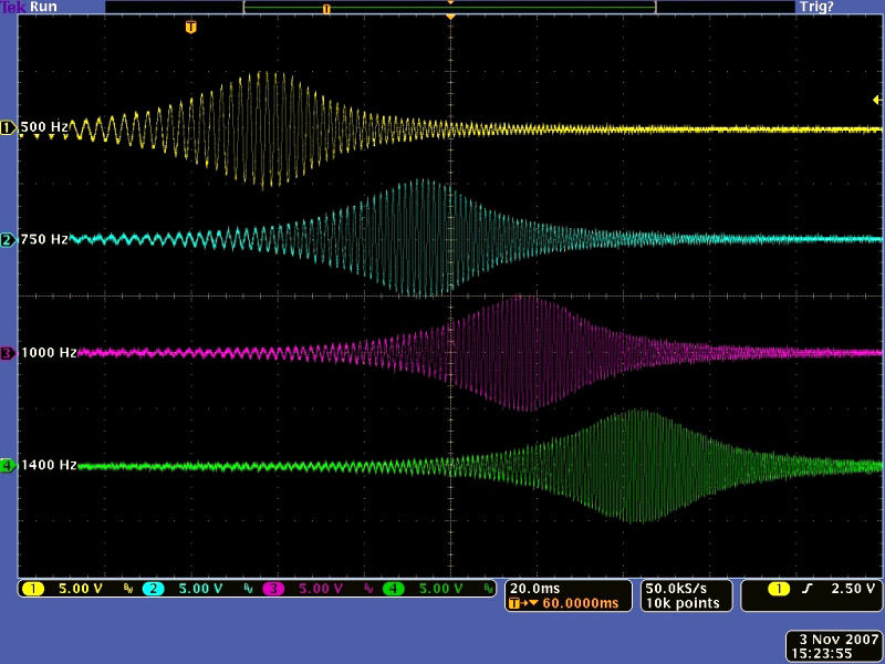
I swept the input to the filter with a sine wave exponentially modulated by a ramp. This scope image shows the output of four of the filter sections and the sharp cutoff of each section as the input sweeps up the frequency range.
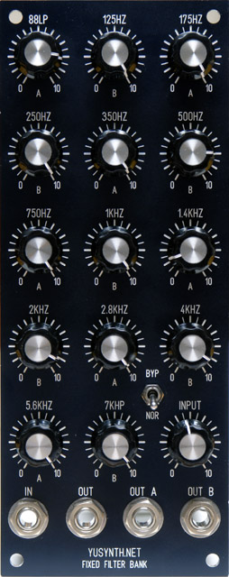
Front Panel Design
I wanted this to fit in a 2U panel so I compressed the control spacing and used smaller knobs. I eliminated the control 'tic' numbers and indicated the even and odd channels with an 'A' or 'B' below each control. I eliminated the second input jack and added an input level control. Small body potentiometers allowed space for a bypass switch to control all three outputs.
Fixed Filter Bank FrontPanelExpress design file