 |
DJB-ComputerVoltageSource |
|
This project is a dedicated build of the ComputerVoltageSource module as a controller for a Kurzweil PC2SRIB ribbon. The PCB is built depopulated to support only the functionality required for control of the ribbon.
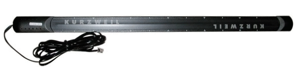
The PC2SRIB ribbon is actually comprised of three segments which interface to IN-2, IN-3, and IN-4. The ribbon measures 6K5 ohms total which would be ~20K each for the individual ribbon segments. I measured the voltage to the ribbon from my Expressionmate controller which consisted of five ~1 mS 5 volt pulses followed by 5 mS of 0 volts at a cycle frequency of ~100 Hz. The CVS powers the ribbon at 5.6 volts from OUT-4 with a diode in series between the ribbon and ground. I do not know the power capability of each ribbon segment so I keep the power in each segment to a low 1.25 mW dissipation. There is more information on the ribbon on my DJB-011 Ribbon Interface module page.
The diode in series sets the ribbon voltage range between 0.6 volts and 5.6 volts. This allow me to determine contact with the ribbon. No contact results in 0 volts on all three inputs. Contact with the ribbon will consist of a voltage between 0.6 and 5.6 volts on one or more of the inputs.
OUT-1 is a 0 to 10 volt control voltage which returns to 5 volts when there is no contact with the ribbon. A 10K potentiometer connected to IN-1 provides an offset adjustment of the no-contact voltage. I generally use a level shift module on the output to provide a +/- 5 volt range and use the offset adjustment so there is no detuning when the ribbon is connected to the FM inputs of a VCO. The output defaults to the right-most position if more than one area on the ribbon is in contact.
OUT-2 is a gate which is active whenever contact is made with the ribbon. OUT-3 is a 15 mS trigger active only on first contact with the ribbon. LEDs on OUT-2 and OUT-3 indicate the status of the gate and trigger outputs.
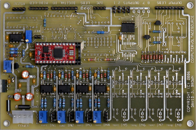
The program has options to be compiled for return-to-center or hold and continuous or quantized output. It can easily be modified to provide inverted outputs, three independent ribbons, or other useful functions. Here is a photo of the CVS ribbon controller using an AtomPro24 processor in one of my original non-solder masked boards. Two jumpers are needed at U4 and U9.
Schematics of the CVS controller for the Kurzweil PC2 ribbon
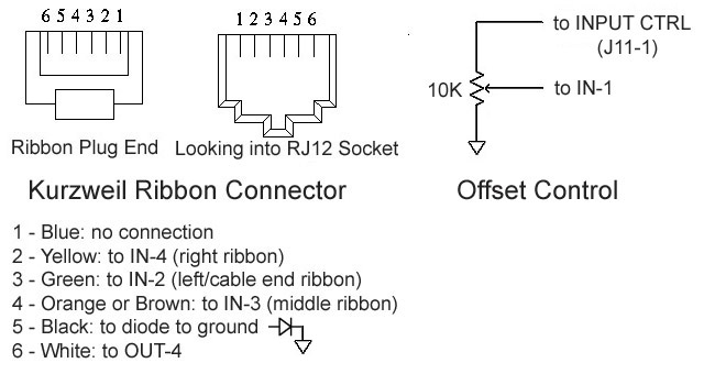
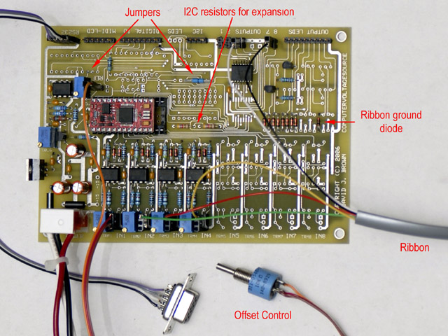
Here is the interface for the Kurzweil PC2SRIB ribbon and the offset control and the completed PCB. I've added the ribbon diode in one of the unused OUT8 locations.
Note: I've had one instance of the wiring of the Kurzweil ribbon connector being exactly the opposite of the chart below. The easiest way to verify the wiring is to find the two pins that have 4K ~8K resistance between them. These are the "ends" of the potentiometer and should connect to OUT-4 and the diode to ground. Identify the three ribbon segments by measuring resistance to one of the "end" pins when that segment is pressed Note that pin 6 is connected to the metal bottom of the ribbon (see below).
Dedicated
CVS PC-2 (rev0.2X).DJB.bas (BMIDE or Studio version)
This program is a Kurzweil PC2SRIB ribbon controller. There are three
variables that are adjusted for specific ribbon and
diode characteristics. The output voltage can be continuous or quantized,
and either held or return-to-center when the ribbon is released. This program should
also run unmodified on a PSIM. My original Kurz PC-2 (rev0.1).DJB.bas
program for the PSIM is on my Programs page.
Repair and Observation
The cable-side section of my ribbon died so I took it apart to see if I could fix it. The plastic end cap on the non-cable side is cosmetic. The plastic end cap on the cable side serves as a strain relief and covers the connection between the cable and the ribbon. The cable is terminated in a 5 pin 0.100" male housing. Pin 6 (white) is also connected to a ground stud but everything is painted so it doesn't make good contact. The ribbon is a flexible circuit sandwiched between two plastic sheets and is glued to the metal bottom. The 0.100" female contacts are pressed through the flexible circuit and crimped. I believe the connection to the conductive ink is made through these crimp fingers.
Since crimped connector for my cable-side section no longer made contact with the conductive ink I cut off the connector, separated the thin plastic sheet that covers the conductive ink, and inserted a small piece of 30 gauge wire with the end stripped to make contact with the conductive ink. I wrapped clear plastic tape several turns around the flex circuit to hold the wire in place. I cut the 5 pin connector off of the cable and soldered the wires directly to 0.100" header pins and inserted them into the contacts. Plastic tape on the metal bottom insulated the pins and I soldered my 30 gauge wire directly to the header pin. I made a new cable clamp that fit on the ground stud. I have no idea why they remove so much of the cable jacket and then heat shrank it. The jacket is fine all the way inside to the connector housing. I wanted to protect the frail flexible circuit board from movement so I covered the wires from to the 0.100" pins in epoxy to fasten them to the metal bottom. It worked!
One observation is that pin 6 white is connected to the metal bottom and I use it for my Out-4 voltage. Swapping it with pin 5 black won't help since that pin is a diode drop above ground. In my setup my ribbon is on my wooden keyboard case and never touches any ground. I don't think that painted stud is a very good connection but I can easily cut that wire if necessary.