 |
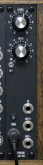
DJB-011 |
|
I have a Kurzweil Expressionmate ribbon that I had interfaced through a PAiA MIDI2CV. I had built a module using the PAiA that level shifted the output to +/- 5 volts through a level control, and mix with external CV and a bias control. This worked fine but the PAiA only had 7 bit resolution resulting in zipper noise. I wrote a MIDI to CV program for my PSIM and found that the Expressionmate used the full 14 bit pitch bend range. The actual resolution is a bit strange as documented below. I decided to design a module using the front panel with an AtomPro24 to interface to the Expressionmate. This ribbon module provides output voltage resolution better than 5 mV per step in a typical configuration. I designed a dedicated controller for just the ribbon using my ComputerVoltageSource module.
DJB-011 FrontPanelExpress design file
Kurzweil Expressionmate
I have seen lots of commentary on the Expressionmate and how the resolution is unsuitable for glides due to zipper noise. I decided to document my experience with the Expressionmate.
The Expressionmate ribbon is actually constructed of three separate ribbons. These are mapped into a single function by the Expressionmate controller. The mapping is not perfect and there are discontinuities between the three ribbon sections.
I measured the absolute pitch bend MIDI data. The lowest MIDI pitch bend message I could read was E0 15 00 (hex) which represents a value of 21 (decimal). The highest pitch bend message I could read was E0 6A 7F (hex) which represents a value of 16,362. The Expressionmate uses the full pitch bend 14 bit range.
What is interesting is that the pitch bend values 'jump' in increments of 15 (hex). This is an odd value as I would have expected a binary increment. Each incremental pitch bend value is 15 (hex) from the previous value. You can get intermediate values depending on where you press on the ribbon, but the increment up or down from this point is always a minimum of 15 (hex). I confirmed this operation by measuring the voltage output of my module. My module software maps the 14 bit pitch bend value over a 10.6 volt range with a 12 bit DAC. Each increment of 21 (15 hex) will be divided by 4 to map to the 12 bit DAC, and each step is 2.6 mV for a minimum increment of 13 mV, or 15.6 cents at 1 V/octave. I measured 3.8100 volts at an arbitrary point on the ribbon, and the next lower value that I could measure was 3.7968 volts, or a delta of ~13 mV.
I rarely use the ribbon with a full 10 volt range as this is 10 octaves of control! I usually attenuate and offset the output to a smaller range. A 3 octave range results in further attenuation by 3.5 which reduces the output voltage steps to 3.6 mV, or 4.3 cents, which is nearly at the accuracy of 'by-ear' tuning. This increment is smoother than I can reliably move my finger on the ribbon.
These mp3 samples are the triangle wave output of my MOTM-300 VCO with the ribbon voltage driving the VCO 1 volt/octave input . The first sample is the full 10 volt range. The second sample is attenuated to a range of ~4 volts. You can hear the two discontinuities at the ribbon transitions points at 1/3 and 2/3 in both samples.
Expressionmate 10 volt glide sample
Expressionmate 4 volt glide sample
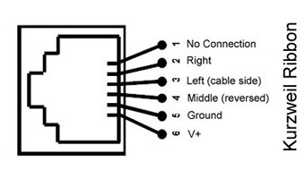
The ribbon (without the controller) is now available as an option for Kurzweil keyboards as a model PC2SRIB. I purchased one from Sweetwater for $49.97. B&H Photo still sells them. Below is the pin out of the mating ribbon connector. It is a 6 pin RJ-11 connector. The V+ and Ground connections are the 'ends' of all three ribbon 'potentiometers'. Note that the middle ribbon section is reversed from the left and right sections. The ribbon is oriented with the cable exiting to the left.
The PC2SRIB ribbon is actually comprised of three segments which interface to IN-2, IN-3, and IN-4. The ribbon measures 6K5 ohms total which would be ~20K each for the individual ribbon segments. I measured the voltage to the ribbon from my Expressionmate controller which consisted of five ~1 mS 5 volt pulses followed by 5 mS of 0 volts at a cycle frequency of ~100 Hz.
I've written a PSIM Kurz PC-2 (rev0.1).DJB.bas program to interface the PC2SRIB to my PSIM. The PSIM powers the ribbon at 5.6 volts from OUT-4 with a diode in series between the ribbon and ground. I do not know the power capability of each ribbon segment so I keep the power in each segment to a low 1.25 mW dissipation.
The diode in series sets the ribbon voltage range between 0.6 volts and 5.6 volts. This allow me to determine contact with the ribbon. No contact results in 0 volts on all three inputs. Contact with the ribbon will consist of a voltage between 0.6 and 5.6 volts on one or more of the inputs.
OUT-1 is a 0 to 10 volt control voltage which returns to 5 volts when there is no contact with the ribbon. A 10K potentiometer connected to IN-1 provides a fine adjustment of the no-contact voltage. I generally use a level shift module on the output to provide a +/- 5 volt range and use the offset adjustment so there is no detuning when the ribbon is connected to the FM inputs of a VCO. The output defaults to the right-most position if more than one area on the ribbon is in contact.
OUT-2 is a gate which is active whenever contact is made with the ribbon. OUT-3 is a 1 5 mS trigger active only on first contact with the ribbon. LEDs on OUT-2 and OUT-3 indicate the status of the gate and trigger outputs.
The program could be easily modified to provide inverted outputs, quantized outputs, hold on last position touched, three independent ribbons, or many other functions.