 |
Magic Smoke Electronics |
|
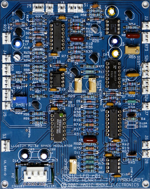
I was able to evaluate the new Magic Smoke Electronics Thomas Henry TH-301 LFO module as discussed on the Electro-Music forum. This LFO design is from his book An Analog Synthesizer for the 21st Century.
My evaluation information and details are located here. My PCB is a Rev1 which requires several modifications documented here. Power consumption: 30 mA +15, 35 mA -15 (both LEDs on) |
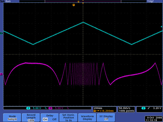
Waveforms and Modulation
This scope image shows the LFO output modulated by a low frequency triangle wave on the FM input.
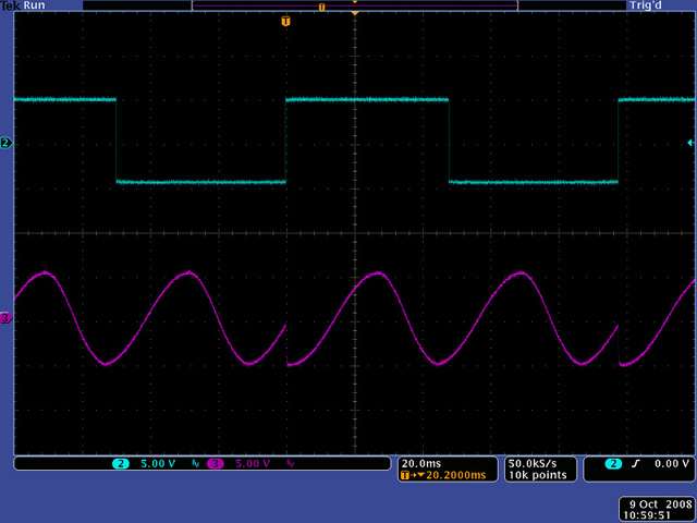
This scope image shows the sine output hard sync'd to a square wave on the sync input. You need fast edges on the sync input. A triangle wave will work if the frequency is high enough.
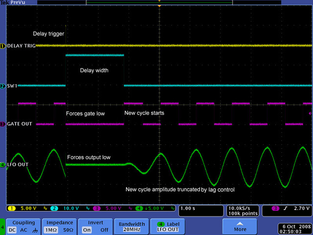
It took me a bit to understand the delay trigger functionality. A delay trigger forces the gate low and attenuates the output until the delay is complete when a new output cycle begins with a new trigger and gate output.
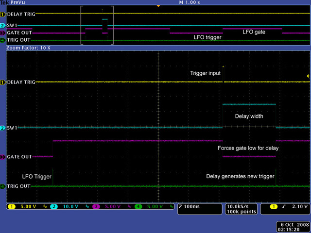
The lag control attenuates the amplitude of the LFO output at the beginning of a new cycle. This image shows a short delay with a short lag. The maximum lag is about 2.5 seconds and the maximum delay is just over 5 seconds.
Construction
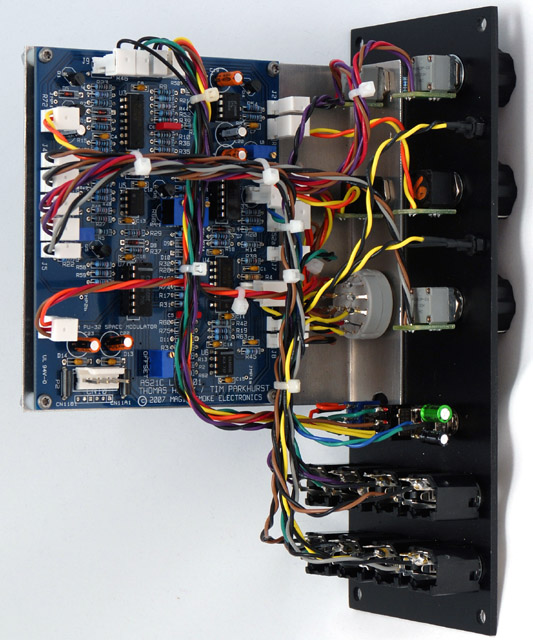
I made an aluminum bracket for the PCB and mounted the timing capacitors at the Range switch. I used a 3 pole 4 position rotary switch to integrate the ramp polarity into the waveform selection switch. I eliminated the Foot Sw jack by combining the functionality and changing to a Gate/Delay switch and a Gate polarity switch. A foot switch connected to the Gate jack operates when the polarity is set to negative. I normalled the Gate jack to ground so the LFO would operate when set to Gate Neg.
TH-301 Gate / Waveform modifications
Front Panel
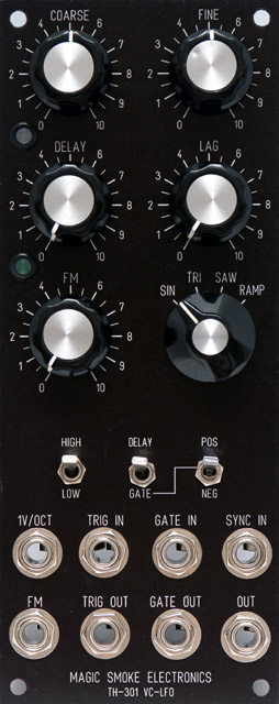
The top LED is a bi-color frequency indicator and the lower LED is a delay indicator. Note the image is an actual photograph of a panel made by gluing a laser print of the FPE design to an aluminum panel and lightly coating with lacquer.
TH-301 VC-LFO FrontPanelExpress design file