|
Circle Machine |
|
I've wanted to make a couple of mechanical modules. One is a Raymond Scott Circle Machine which he designed in 1959 and the other is a Hammond Vibrato Scanner. I completed my mechanical Hammond vibrato scanner and also a Jürgen Haible electronic scanner chorus/vibrato module so it was time to work on the Circle Machine.
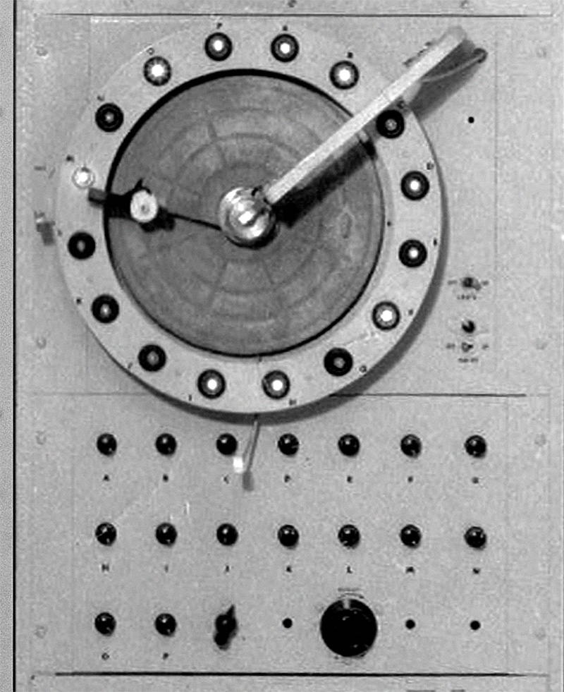
I started with only this small obscure small photo. I didn't know anything more than it had lights and spun. The Manhattan Research CD has an introduction by Raymond Scott with this information - "At the tip of the arm there is a photo cell. This cell is a part of an electronic sound generating system, so adjusted that the more light the cell 'sees' the higher the pitch of the sound produced. The cell also moves around in a circle at adjustable speeds. One of the controls, above the circle of lights, changes the pitch center of the complete cycle when required."
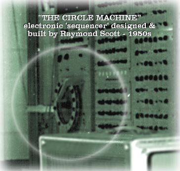
Photo courtesy of the Raymond Scott Archives
This project is referenced on several websites and blogs:
- My posting on Muffwiggler Forum
- Raymond Scott part 1 and part 2
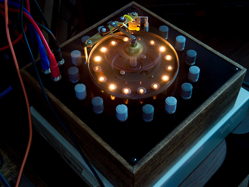
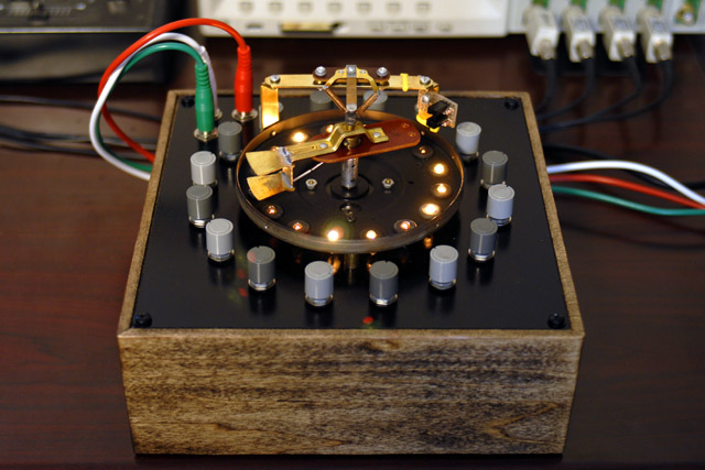
Here's a photo of the finished Circle Machine that I really like.
Overview
I built this Circle Machine using 16 lamps and rheostats, motor, armature-sensor, and slip-disc. The Hammond vibrato scanner has an excellent slip-disc mechanism that I wanted to use so I mounted the round base on a 5Ux5U panel along with the lamps, rheostats, and control jacks. The motor and lamps require 1.25A of +12V so I used an external power supply for the mechanism. I made a separate bracket to mount the slip-disc pickup since it mounted on the vibrato scanner cover and I didn't want to enclose the inner workings of the Circle Machine.
Most parts were from my junk box. The motor isn't quite large enough and the mass of the armature causes a "bounce" at the end of each step. The CdS sensor "go dark" time is rather quick and the "go light" time is rather slow. Like the original there is a drop out or "dead zone" between lamps. If you listen to recordings of the original, the sounds are short bursts and the pitch seems to change at the end. I can think of three ways Raymond might have dealt with this dead zone.
(1) The CdS sensor might have been in series with the power supply with an oscillator such that higher voltage resulted in a higher pitch. The "dead zone" between lights could simply be where the voltage was low enough to not oscillate.
(2) There could have been some threshold level detection on the output of the sensor to create a gate.
(3) Since it is motor driven, there easily could have been a 16 tooth cog wheel and microswitch which created a gate.
I removed three of the vanes and the counterbalance weights to lighten the armature. The lower vane supports the CdS sensor. I used an optical sensor to determine the position of the top vane at power-up. With a stepper motor I know exactly when the arm is over the light so I simply sample and hold the output. This also allows me to scale and quantize the output.
It is slow to tune since you have to tune on the fly. I thought of adding a single step function but the CdS sensors have a lag so tuning while static produces a different pitch then reading the light while spinning. I do however display the note pitch on the LCD display. Note however that incandescent lights are non-linear and not all lights output the same brightness. Like the original, this is mostly to produce sound effects rather than specific pitch sequences.
I chose small lamps so I could use 500R potentiometers to control the brightness. I run the lamps on a slightly reduced voltage to maximize life. Reading the lamps from the top and painting the mechanism black eliminates issues from ambient room lighting.
I chose to use my four channel ComputerVoltageSource or PSIM to control the Circle Machine by generating the clock for the stepper motor and processing the output control voltage. Three cables are required between the Circle Machine and the ComputerVoltageSource. The program samples the CdS sensor and inverts and scales it to generate the control voltage. I quantize the output and have a Tune control which adjusts the sequence +/- 12 semitones.
The Sequence Length control sets the sequence to 4, 8, or 16 steps. I simply skip reading the in-between lamps on the shorter sequences. Since the rate does not change, the tempo drops for the shorter sequences (8 at 1/2 and 4 at 1/4 tempo).
|
Circle Machine program |
|||
| Jack | Function | Jack | Function |
| In-1 | Rate | Out-1 | CV Out |
| In-2 | Sequence Length (4-16) | Out-2 | 50 mS Trigger (per lamp) |
| In-3 | Tune (+/- 12 semitones) | Out-3 | Home (lamp 1 position) |
| In-4 | CdS sensor | Aux | Stepper motor clock |
| Start | Home sensor | Stop | Quantize (on/off) |
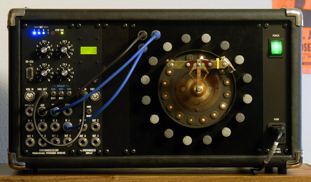
Since the mechanism is a 5U x 5U panel, I can mount the PSIM, PSIM Display, and Circle Machine into a rack cabinet.
Rack space is precious so I also made a wood case to house just the Circle Machine. This is my preferred configuration.
This video shows the completed Circle Machine in operation. I use a voltage control from an LFO to drive the sequence length. The changing of the sequence length adds an interesting effect as the shorter sequences occur at 1/2 and 1/4 tempo. The CV output is driving my Living VCO which is tuned to disharmonious notes, and then run through a low pass filter. The envelope for the low pass filter is controlled by the Circle Machine trigger. The LCD displays the step number, sequence length, and note number (if quantized) along with the sequence length CV (displayed at the end of line 1).
This video shows another demo of the Circle Machine. I again used a voltage control from an LFO to drive the sequence length. The CV output is driving my Living VCO which is run through my Resonant Lopass Gate, 3.35" tape delays, and a spring reverb. The envelope for the Lopass Gate is controlled by the Circle Machine trigger.
This video uses the Circle Machine to generate a sequence for a demonstration of the the Polivoks filter grunge factor. Here is a quick video of it in action.
I built this Circle Machine fun since I thought it would be visually interesting. I didn't intend for this to be a precision sequencer nor a faithful recreation of the Raymond Scott Circle Machine. It does include voltage control of pitch offset in semitones over +/-1 octave, similar to the original. I did add voltage control of the speed and of sequence length. I am pleased with the results, it works well generate sequences, and is fun to watch.
Construction Notes
I used a Howard 1-19-4203 stepper motor which will do 3.6º steps and 1.8º half-steps. I built a separate stepper motor control circuit so I just have to provide a clock. After this photo was taken I added a bit more circuitry for the home and CdS sensor.
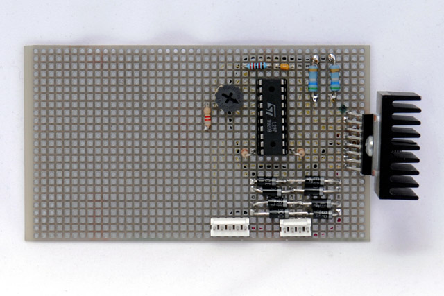
Stepper motor and control schematic
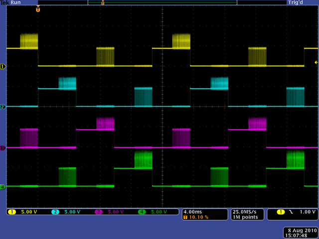
The L297 stepper motor controller limits the current by chopping the motor drive phase signals. This scope image shows the chopping on all four phase drive signals.
I tried stepping rapidly to each lamp and then pausing. This video demonstrates an 8 step sequence by stepping lamp 1 thru 8 and then returning 180º back to the beginning of the sequence. The time required to return the lamp 1 position was significant so I had to adjust the various step delays to keep an even tempo. I eventually changed to skipping lamps for a 4 or 8 note sequence.
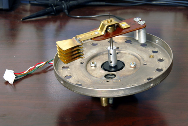
I had to machine the center of the Hammond vibrato scanner base plate to mount the stepper motor. I also had to machine a coupler to adapt the stepper motor shaft to the armature shaft. This photo shows the modified base plate and the armature prior to removing the three vanes and counterbalance weights.
I mounted the CdS photoresistor on the bottom vane of the armature. I used #2174 12 volt 40 mA lamps and pressed them into grommets in the base plate. The lamp brightness diminishes to very dim with a series resistance of ~500 ohms. I characterized the lamp power with a series resistor and the maximum power dissipated is 170 mW. This allowed me to use 500 ohm ½ watt linear taper potentiometers as rheostats to control the brightness of each lamp.
This photo shows the painted base plate with the bracket for the slip-disc pickup and 6 lamps installed.
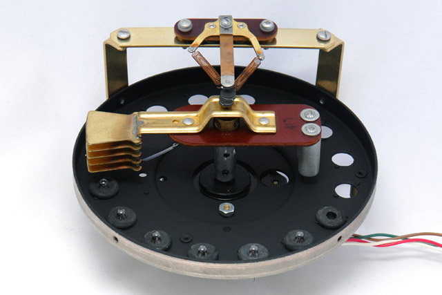
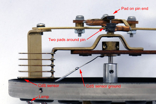
This photo shows the Hammond vibrato scanner slip disc. It is very well designed using three carbon pads - one to press on the top of the pin and two that slip over the pin and are held with spring tension. This slip-disc was designed to pass audio so it passes a clean sensor signal. This photo was taken before I removed the middle three vanes.
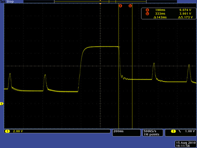
The sensor settling time is about 140 mS which is too long for a 16 note sequence less than 2.25 seconds long. I chose to change the operation of the stepper motor to a constant delay per 1.8° half step and sample the CdS sensor "on the fly". This minimized the bounce and provided a fairly repeatable sensor reading during the transition time. This scope image shows the faster "go dark" and the slower "go light" response times as well as the bounce of the armature.
This video shows the scanner base temporarily wired up 6 lamps with fixed resistors and a 225º return to the beginning of the sequence. The photoresistor forms the bottom half of a voltage divider that I scale, offset, and run through a lag circuit to generate the control voltage for a VCO. I later eliminated this external processing by sampling the CdS sensor and processing the output with my controller.
This video shows the Hammond vibrato scanner base mounted on a 5U x 5U panel with 8 lamps and 16 potentiometers. It is playing an 8 step octave sequence from C3 to C4. There is a lot of equipment running in the background so the audio is not as clear.
Epilogue
I built my Circle Machine in 2010. In 2018, 8 years later, I obtained this photo taken by Raymond Scott.
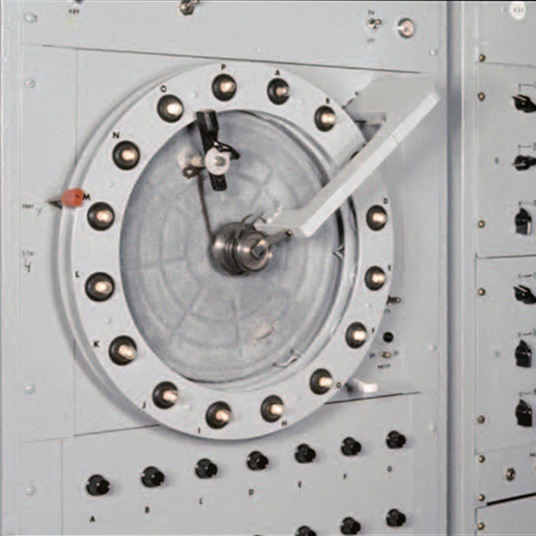
Photo courtesy of the Raymond Scott Archives
Based on this better photo showing the mechanism I have new thoughts on how it might have operated:
(1) The bulbs are read from the side. When reading the top lights the sensor is pointed directly at ceiling light so ambient light must have affected this. However, I don't think it was a precise pitch device and one would simply adjust the rheostats for the desired pitch. Sequences were short so the ambient light was probably constant.
(2) Raymond's introduction describes an arm but I don't see the sensor mounted on an arm. Instead the sensor appears to be mounted directly to the panel.
(3) The bar on the left appears to be the mount for the brushes for the slip rings for the sensor output. There are two visible brushes and I suspect these are in parallel to reduce noise since. There is also what appears to be a darker shadow where bar comes near the panel indicating there is a gap between them. The bar is massive and would not need to be if it were mounted on both ends. The wire between the sensor and the slip rings has a twist in it and appears to simply be an electrical wire. The photo to me indicates the sensor was mounted on a platter that spun.
(4) The platter has a pattern. This pattern is similar to the casting on turntable platters. It doesn't appear to be a standard rack panel.
(5) The Raymond Scott Festival had a wall with a face on view of the Circle Machine (see below). In both of these recent photos the controls appear to be below the Circle Machine. However, they appear to be built on two different panels so they could be oriented in any order. Perhaps at one time they were reversed.
(6) I have no idea what the small red knob at the M position is for.
Note that others who saw the Circle Machine in operation said it had a rotating arm and Raymond's introduction describes an arm. I just don't see one in this photo but we don't know if Raymond had a different version or modified it at some time. Either way this is truly a work of art. Additional information of the Circle Machine has been posted at the Encyclotronic Electronic Music Archive.
2018 Scottworks - The Raymond Scott Festival
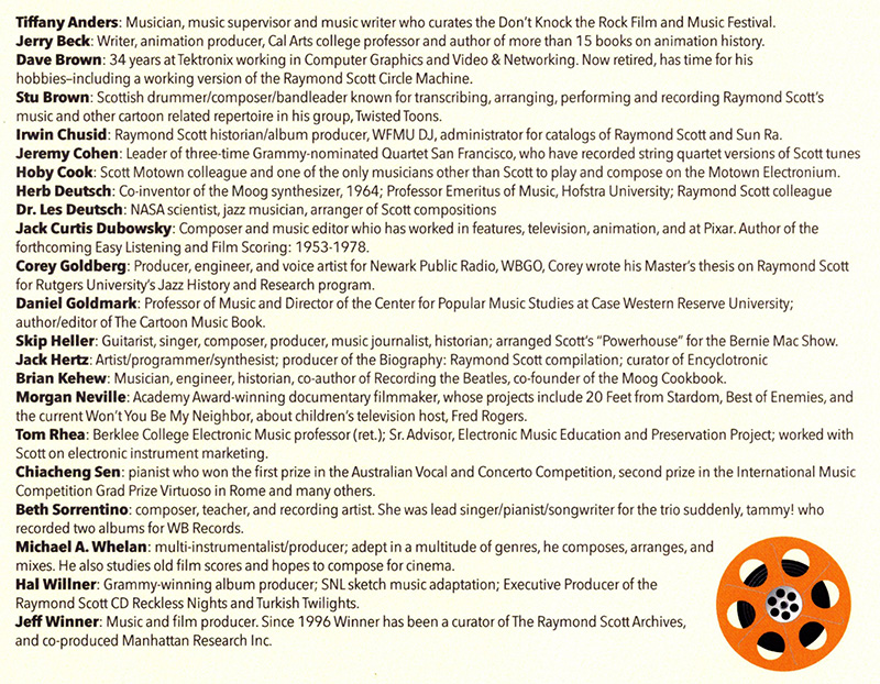
8 years after I built the Circle Machine I was invited to exhibit it at the 2018 Scottworks - The Raymond Scott Festival on September 8th at the Colony Theater. Here are the presenters that were at the festival.
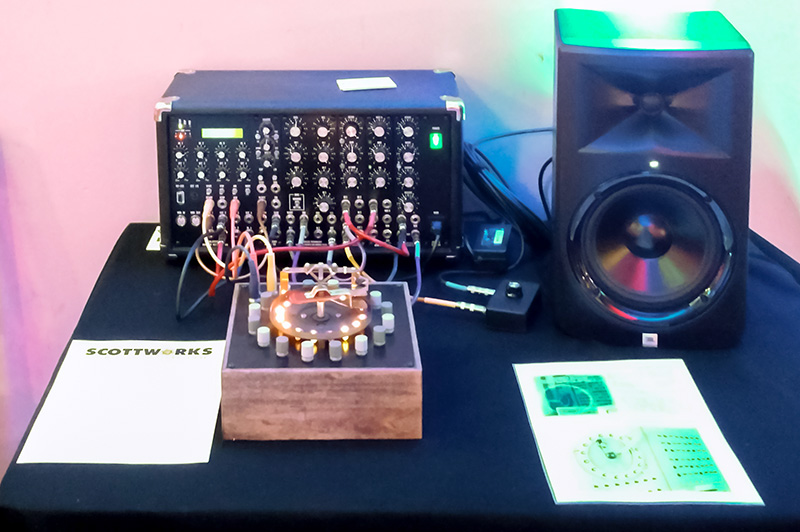
Here is my Circle Machine exhibit and the signage. The cabinet consists of a 4 channel ComputerVoltageSource to control the Circle Machine, my CEM3340 Maximus VCO, a MOTM-440 VCF, a MOTM-190 VCA, a MOTM-390 LFO, and a MOTM-890 Envelope Generator. I used the Circle Machine trigger to drive the Envelope Generator to modulate the VCF and VCA. The LFO provided a random input to the sequence length to modify the pattern.

I got my photograph taken seated at "the wall".
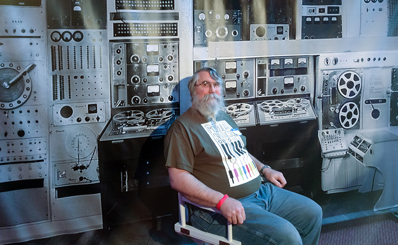
The wall has another view of the Circle Machine and shows the entire control panel.