 |
Three Cabinet Moog Restoration |
|
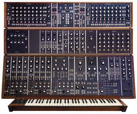
I had the opportunity to restore a three cabinet Moog and chose to document each module with photos and information. I was surprised there were so many errors in the schematics. I ended up going back to the original blueprint schematics as they are much better.. There is a Muffwiggler topic Saying goodbye to an old friend (first modular) for this synthesizer and others started two new topics Dave Brown's awesome Moog restoration! and Large modular restoration with great pictures. The sales history for a few of the module serial numbers are from a system shipped to Electric Lady Studios for Jimi Hendrix in 1969.
I strived to keep the repairs as original as possible. I used period-correct resistors and ended up hand selecting quite a few for the oscillators and envelope generators to meet specifications. There were a number of modifications made over the years that I removed and restored to original functionality. There were some electrical problems but quite a few electro-mechanical problems. Switches and jacks no longer made contact, trimmers were intermittent and wires were broken. Some resistors had drifted, some capacitors were leaky, and a few transistors were dead, but for 45+ years old the modules were in respectable condition.
Some of the Moog modules such as the 960 Sequential Controller, 961 Sequencer Interface, and the 962 Sequential Switch use 700 series RTL (resistor-transistor logic) for logic. Of course nowadays RTL stands for register transfer level but the 700 series was the first commercially available low and medium scale integrated logic introduced in the early 1960's and is relatively hard to find. RTL operates on a +3.6V supply so some of the V-Trigger outputs are only 3.6V.
The modules operate on +12V and -6V and the VCOs also require -10V. Power and other connections are made through a Tyco Duo-Tyne flag 22 pin edge connector which has zero clearance past the end pads (i.e. no PCB material extending past the last pad). My first task was to make a power cable so I could operate the modules on the bench. I used a standard 22 pin EDAC series 306 22 pin edge connector and filled the gap on either end to fit and center on the PCB fingers.
These systems are rare. My best estimate of the purchase price of this synthesizer in 1969 was around $9,400. I used these two price lists and extrapolated the prices to 1969 dollars. In 1969 an average car cost $3,270 and the average wage was $5,894 so this synthesizer cost nearly 2 years wages.
1976 Moog Module Price List Note that this price list is in Canadian dollars but the exchange rate in 1976 averaged 1.0144 CD/USD
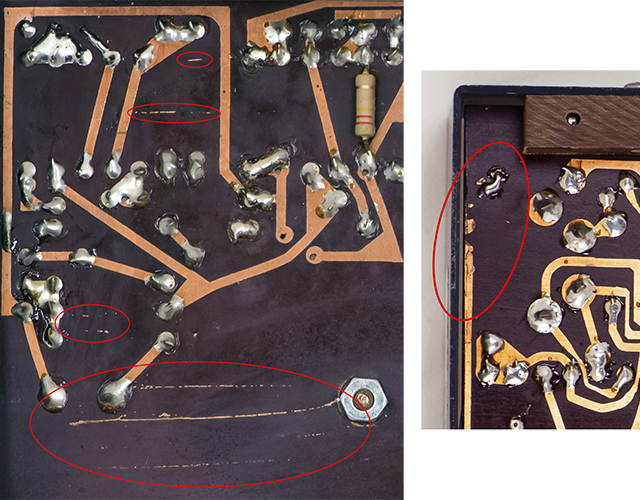
I was surprised to see etch problems on two PCBs although these modules are quite early for PCB production. The missing run on the right was jumpered on top with holes drilled through the PCB so they took some care in the repairs.
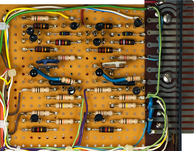
I was also surprised to see a completely hand-built module on a perf board.
Moog Top Cabinet
The top cabinet consists of two 960 Sequential Controllers, a 961 Sequencer Interface, two 962 Sequential Switches and a power supply. There is also a custom panel consisting of two 4 jack multiples and 3 jacks which are wired to the rear of the cabinet.

Hi-res photo of Moog top cabinet front
The original Moog power supply had been replaced with a Power-One, an IEC mains connector, and a fuse.

Hi-res photo of Moog top cabinet rear
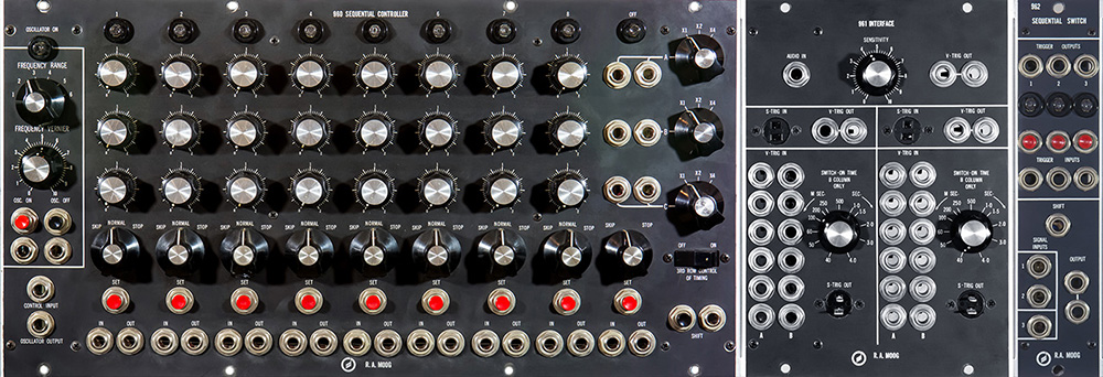
This video demonstrates synchronizing two 960 Sequential controllers on the same clock, using a 961 Sequencer Interface to shorten the number of steps in a sequence, and using a 962 Sequential Switch to multiplex the 3 parallel outputs to a serial output.
Moog Middle Cabinet
This middle cabinet is powered from the bottom cabinet and contains a fixed filter bank, three voltage controlled amplifiers, envelope follower, dual trigger delay, envelope follower, three envelope generators, reverb, and a four channel matrix mixer.

Hi-res photo of Moog middle cabinet front
The large cable across the bottom is for power from the bottom cabinet. The short cable on the left is for power to an alternate controller.

Hi-res photo of Moog middle cabinet rear
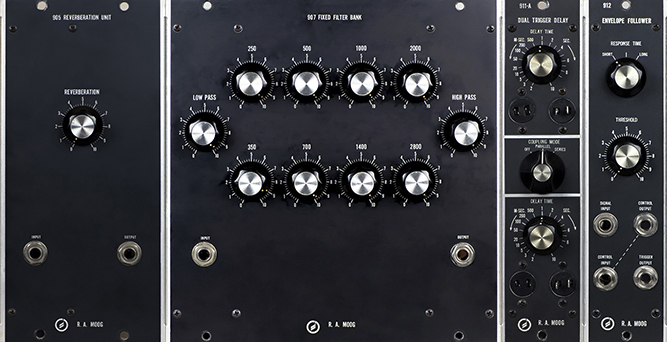
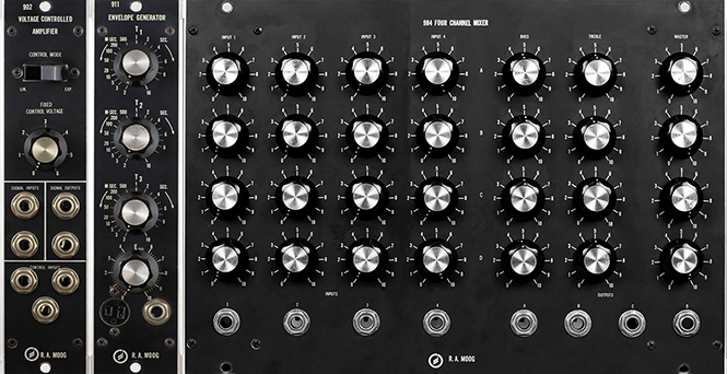
902 Voltage Controlled Amplifier
Moog Bottom Cabinet
This bottom cabinet contains the trunk and controller bus wiring and a power supply. It contains seven oscillators, low pass and high pass filters, noise source, two voltage controlled amplifiers, and two envelope generators.
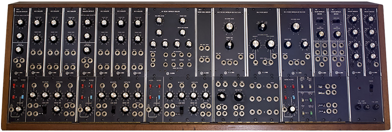
Hi-res photo of Moog bottom cabinet front
The original Moog power supply had been replaced with a Power-One for the +12 and -10V supplies. The two small perfboards supply the -6V. The mains connector was replaced on the rear panel with an IEC connector and a small bracket added for a pitch and trigger jack wired in parallel with controller 2. Only a few of the original serial number labels remain. The wire ties on the right side of this cabinet have been removed so the 901 and 901A modules can be pulled forward for tuning.

Hi-res photo of Moog bottom cabinet rear
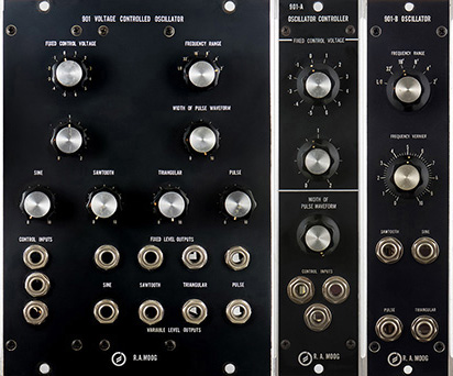
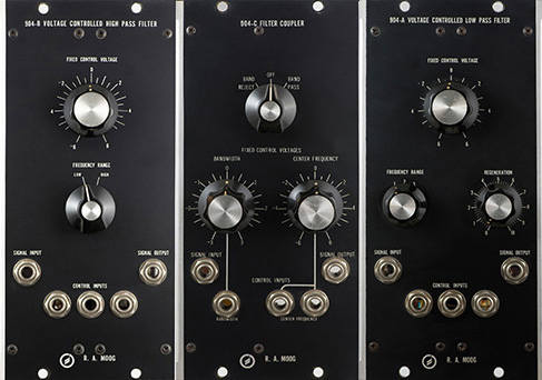
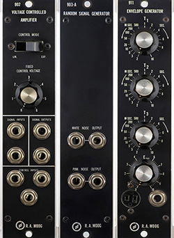
902 Voltage Controlled Amplifier
The Console Panels consist of a model 2 panel with passive filters and pitch and trigger jacks, three model 3 panels with CV routing and a four input mixer, a modified model 4A panel with CV and Trigger routing and trunk multiples, and a model 8 power panel.
